

After completing a dyno tune on my mildly stroked S38, I am still working to dial in the ITBs on the M5. The ECU was hunting just off idle and depending on where it was in its cycle it would "jerk" slow speed transitions. We didn't spend a lot of time on the dyno working the idle and low RPM range as I was not confident my ITBs were properly synched before we started.
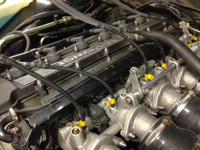
I am getting close after chasing a couple dead ends, so thought it might be beneficial to share my experience and pick up any extra tips. Because the new engine uses a MAF (hot wire) instead of a more restrictive AFM (spring loaded flap), the engine is much more sensitive to idle air leakage through the butterflies and bypass screws. I am sure the higher compression and increased stroke also plays a part.
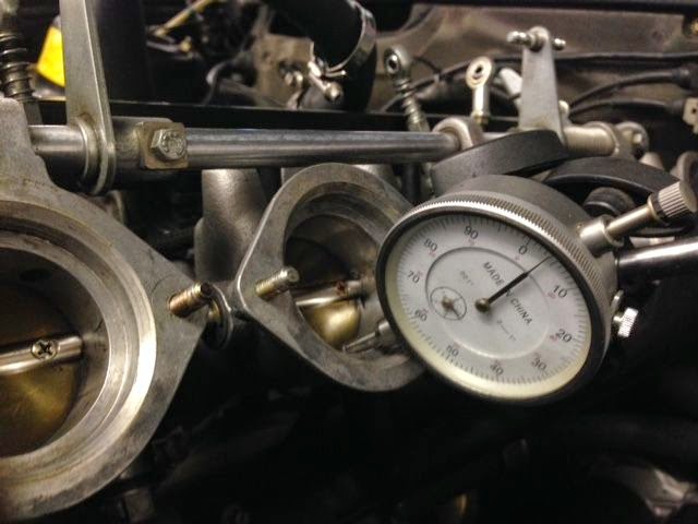
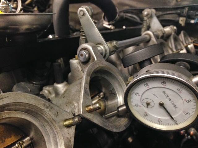
The factory set the butterflies with a resting position of .010. Zero is set where the butterfly is fully closed into the housing. A dial indicator is positioned at the leading edge of the butterfly and a stop screw is cranked until you get a .010 reading. All three pairs of ITB are set in the same way. Unfortunately this is too much free air flow for the ICV and bypass system, so the small needle valves on each ITB are ineffective as tuning individual contributions.
I have been reducing the opening of the ITBs far enough in order for the needle valves to have an effect. When I started at .010 you could move the needle valves and there was no change in engine tune.
I have been setting the mechanical adjustment by removing the manifold/trumpets and using the dial indicator. Not difficult but fiddly with all the little nuts and tight spaces. I noted a significant improvement by tightening the clearance to .005, and then made a further adjustment by "feel" to .003. The final setting has the potential to change a bit when the linkage is reinstalled and all three ITB pairs are linked. Instead of setting up three dial indicators I ordered stack of .002 and .003 feeler gauges from McMaster Carr so I can ensure that the linkage does not change the static setting of each ITB. For the final mechanical adjustment, I'll set the stops, install the linkage and ensure all six shims have equal drag. I plan on cutting the shims to ensure I am not introducing issues with the curve of the barrel. They are mechanically close now, but I need one more final pass.
I tried three methods to balance the ITBs with the bypass screws.
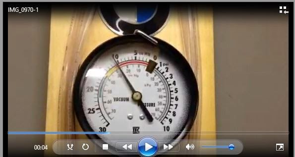
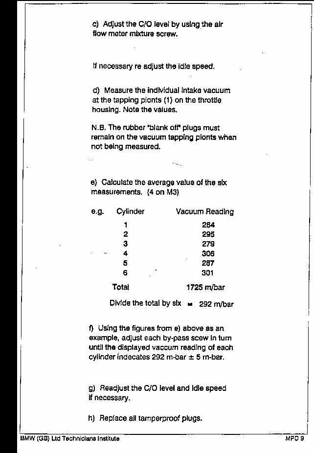
1. The manual instructs you to install a vacuum gauge to the ported ITB and record the value. Move the gauge to each ITB and repeat and average the result. Complete repeating this process until all values are close... I found this impossible as the idle speed changes as you make adjustments and invalidates the previously recorded values. A complete waste of time. I thought I could improve in this by buying 6 vacuum gauges. Each required a dampener needle valve to keep the gauges from bouncing. Then I found that they were not calibrated the same (a friend warned me about this), so I disassembled the gauges and hooked them to a common manifold and pulled a vacuum from a small HF pump I used for my AC, and reset the needles. They were then calibrated at a specific vacuum, but were our of spec outside of a narrow range. All this really determined is what we all know - Chinese gauges are junk. On to method two.
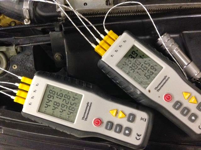
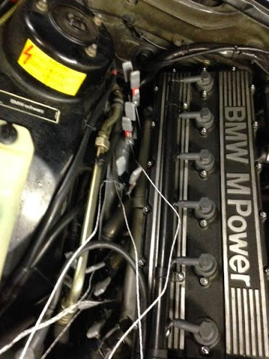
2. An S38 guru, suggested that I use exhaust temperatures. I tried using an IR gun, but short of burning my hand to ensure I was pointing at the right pipe, this was more inconsistent then the individual vacuum gauge approach. Not learning from my experience with the vacuum gauges, I found an instrument that can measure four individual readings at one time. I bought two (good for 8 readings) and made clamps to hold the k-type sensors to the outside of the exhaust tubes. Temperatures varied by 50-80 degrees and large adjustments to the bypass screws, so big that you can hear/feel cylinders working or shutting off, didn't seem to make any differences to the temperatures. I gave this a really good try, repositioned the clamps several times (ouch) and finally gave up when I realized that all I was measuring was the thickness of my ceramic coating and perhaps the distance from the exhaust valves. Given my euro headers have no provisions for EGT ports (the US exhaust manifold does), and removing them to weld bungs would be almost impossible without dropping the engine this was a hill too hard to climb. Besides I started to wonder how effective exhaust temperatures are at idle with the engine completely unloaded. So, besides determining that ceramic coating works, all I can conclude is this was great way to burn your hands. On to method three.
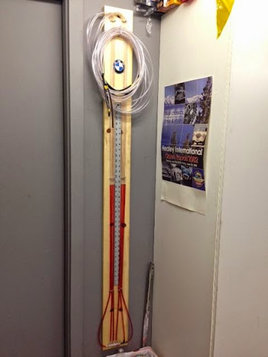
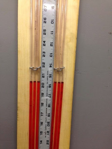
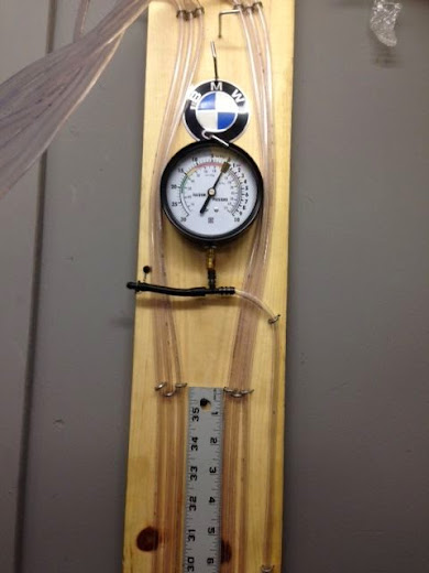
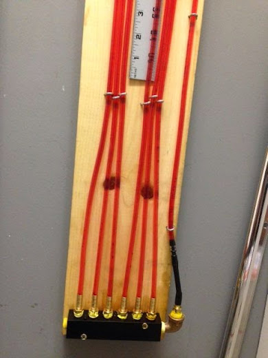
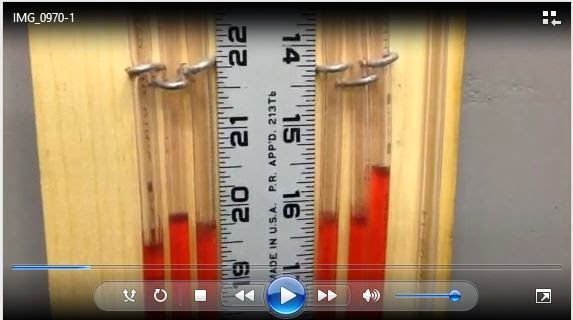
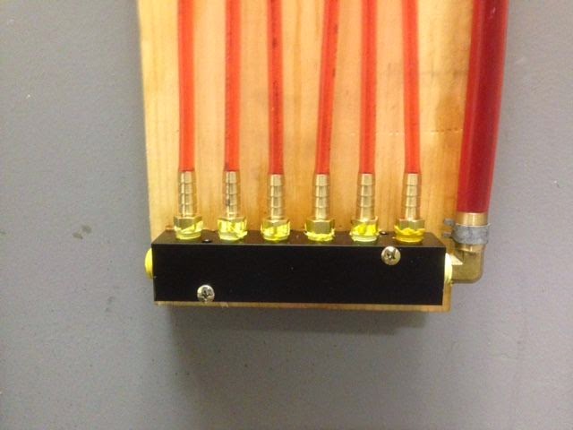
3. I had a discussion with a friend that manages large ship engine installations. He said they use manometers, or mercury u-tubes to measure absolute vacuum. I spent a few hours searching for mercury and although I found a few sources, as I learned more it seemed that the EPA would be knocking at the door. I found a motorcycle tool that measures relative vacuum. This eliminated the mercury issue and resulting jail time. I found a DIY site that I extrapolated that to a six cylinder ITB application. 100' of tubing, a little Marvel Mystery Oil and a few staples in a board resulted on a tool that seems to have real value. I was able to quickly turn the bypass screws and watch the fluid rise and fall. I ordered some fancy parts from McMaster Carr to make it a better tool with a common aluminum manifold and provisions for filling, draining and adding a vacuum gauge, but as it is it seemed to perform well. Finally!
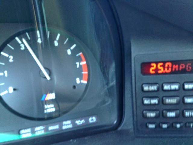
A short test drive to the snake and pretending to creep along in traffic convinced me that it is just about perfect.
So the M5 will need the mechanical throttles adjusted one more time with the shims and I should then be able to perfect the balancing with the manometer. And capping off two of the ports should allow me to use it on the Lotus.
I am anxious to return the LM-2 back to it's case or move it to the Lotus.
What have I missed?
Dean
Edited to fix the pictures...