Rebuilding My 1988 US-spec M5
-
austin8753
- Posts: 1491
- Joined: May 16, 2010 1:37 AM
- Location: Portland, Oregon, USA
Re: Rebuilding My 1988 US-spec M5
Awesome, subscribed.
Re: Rebuilding My 1988 US-spec M5
HAHAHA. A pro would do the work and end up with more money in their pocket. I do the work and the money just flies away.muleskinner wrote:Comments from the BaT auction:
"Excited to have won this one. I went drove down to LA this weekend to look at the car in person and drive it. From my non-pro mechanic’s POV,"....
Coulda fooled me. Looks pretty damn professional.
Re: Rebuilding My 1988 US-spec M5
Fantastic work. Subscribed!!!
Re: Rebuilding My 1988 US-spec M5
Re: Rebuilding My 1988 US-spec M5
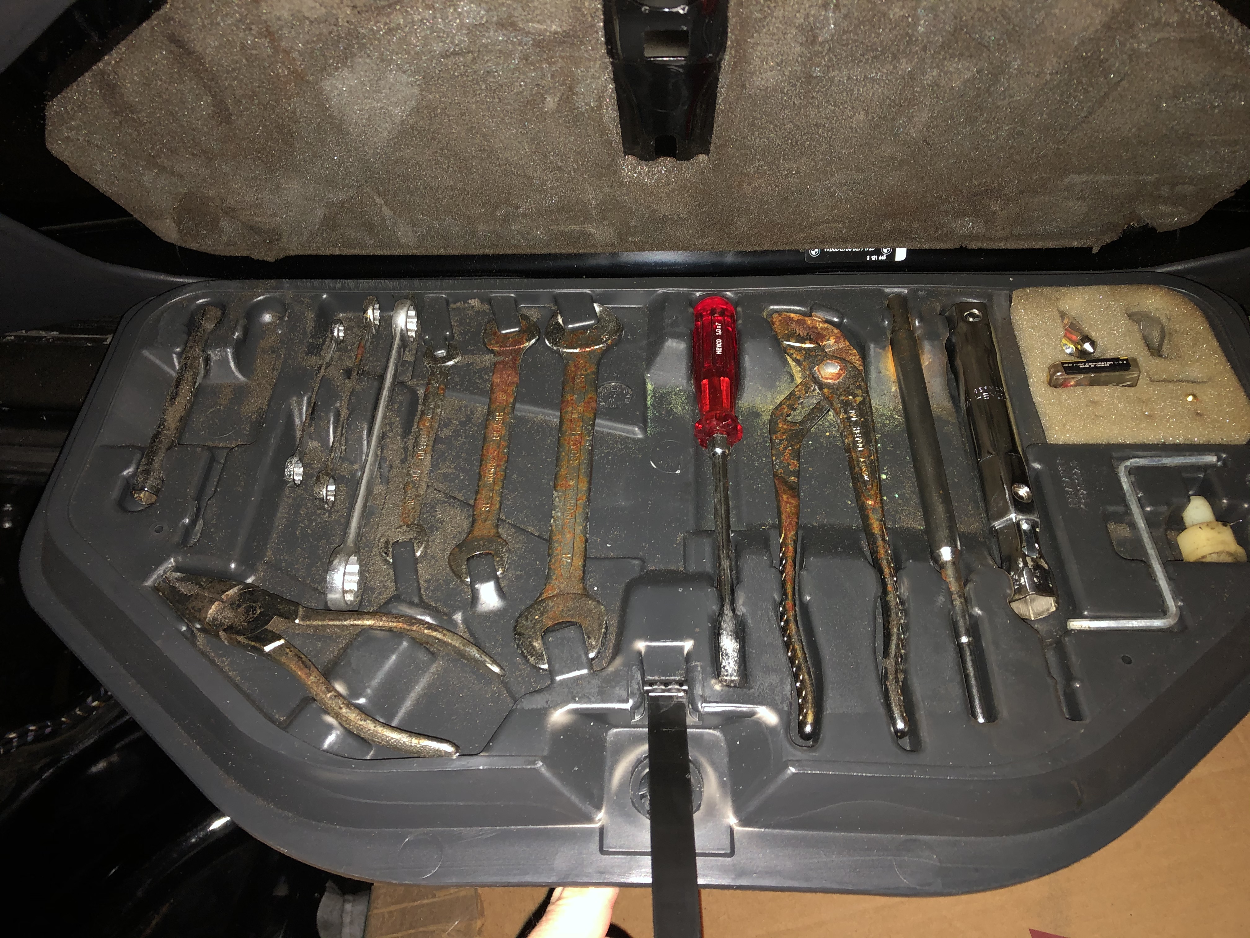
Not a huge update on progress, but I'll file this one under "small victories." When this car was originally up for auction at BaT, a number of commenters noted the "rusty" tools and surmised that there must be rust in the trunk, because the same moisture that rusted the tools would have rusted stuff in the trunk. At the time, I'd gone & looked at the car personally, and I didn't see anything in or around the trunk area to give me concern. As far as the tools were concerned, I'd sort of just mentally added to my list that I should be on the lookout for a new - scratch that - replacement set on eBay.
After watching eBay for a while and realizing that buying replacements was going to be an expensive PIA, I decided to see if the existing tools would clean up.
Before:
After:
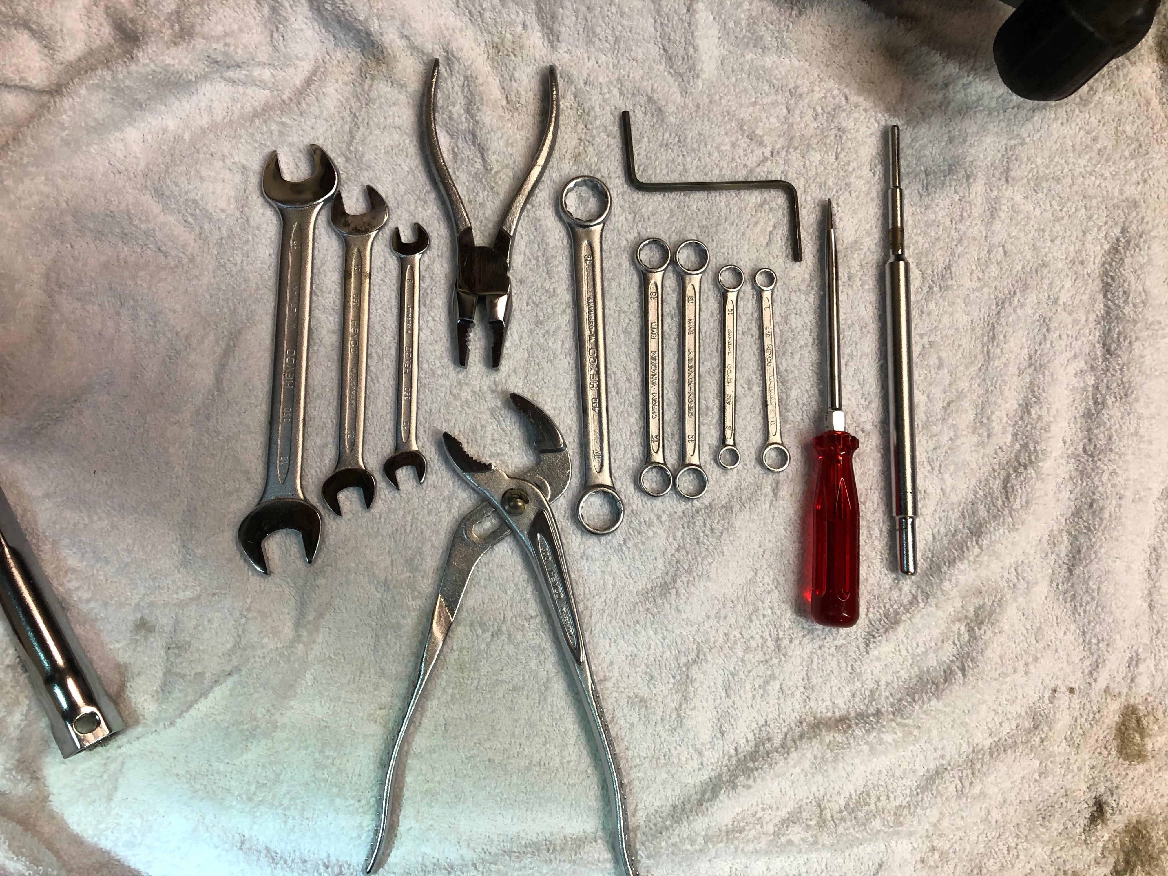
Not perfect, but I had a "wow" reaction. I sprayed the tools with the POR-15 "metal prep" product (I think it's basically a rust remover?) and scrubbed them a bit with a green Scotch-Brite sponge and also with a brass brush while they were soaking.
I'm pretty sure most of the brown spots that looked like rust in the BaT photos were actually stuck-on foam from the trunk pad that had disintegrated and stuck to the tools - maybe heat caused it a bit? As it turned out, there was actually very little rust on the tools. Winning!
I still need a small red-handled screwdriver ...
After watching eBay for a while and realizing that buying replacements was going to be an expensive PIA, I decided to see if the existing tools would clean up.
Before:

After:

Not perfect, but I had a "wow" reaction. I sprayed the tools with the POR-15 "metal prep" product (I think it's basically a rust remover?) and scrubbed them a bit with a green Scotch-Brite sponge and also with a brass brush while they were soaking.
I'm pretty sure most of the brown spots that looked like rust in the BaT photos were actually stuck-on foam from the trunk pad that had disintegrated and stuck to the tools - maybe heat caused it a bit? As it turned out, there was actually very little rust on the tools. Winning!
I still need a small red-handled screwdriver ...
Re: Rebuilding My 1988 US-spec M5
Hi,
There is a gentlemen in Suffolk / Norfolk (UK) who makes up replacement foam pads that fit between the tool tray and the boot lid (large and small) as they are NLA from the main stealers:
https://www.ebay.co.uk/itm/BMW-E30-316- ... Sw3fZcWliz
I have had two of his E28 large tool box foam inserts and found then to be a good replacement option.
I recommend his product without reservation.
Regards,
Mick
-
Adam W in MN
- Posts: 5052
- Joined: Feb 12, 2006 12:00 PM
- Location: Don't waste my motherf***in' time!
- Contact:
Re: Rebuilding My 1988 US-spec M5
This is a great thread! Lots of thoroughness going on and overcoming the unexpected surprises (like that speaker install).
Re: Rebuilding My 1988 US-spec M5
Thanks and good to know. I'll check that out. I'd actually already bought the foam pad for the E24 (I think it was P/N 71111113754). I'd been told that it's a *very* close match, but when I held the new E24 pad up to the old one that's in the car, it looks identical - same color, shape, holes, etc.Ordnator wrote:Hi,
There is a gentlemen in Suffolk / Norfolk (UK) who makes up replacement foam pads that fit between the tool tray and the boot lid (large and small) as they are NLA from the main stealers:
https://www.ebay.co.uk/itm/BMW-E30-316- ... Sw3fZcWliz
I have had two of his E28 large tool box foam inserts and found then to be a good replacement option.
I recommend his product without reservation.
Regards,
Mick
Re: Rebuilding My 1988 US-spec M5
Ha. Thanks. So far, I've only discovered the problems. Haven't worked up the courage to fuck them up mo ... I mean fix them. I hate bodywork.Adam W in MN wrote:This is a great thread! Lots of thoroughness going on and overcoming the unexpected surprises (like that speaker install).
Re: Rebuilding My 1988 US-spec M5
I actually managed to get a few things done this weekend. I'mnot sure if the M5 is really that much more complicated, or if I'm just not being as thorough about ordering my parts thread of time, but I seem perpetually to be one-part-shy of having the next major assembly done.
Until this weekend, that is. With freshly replated M9 bolts (black oxide at Arrow Plating), I had everything in hand to rebuild the brake calipers. The one thing that was bugging me was that in my limited experience, clear zinc plating can sometimes be tough to clean. But I didn't want to try to get these calipers powder coated (either color or clear) cause time & $$$, so after research I found this stuff at Eastwood: two-part, high temp clear coat.
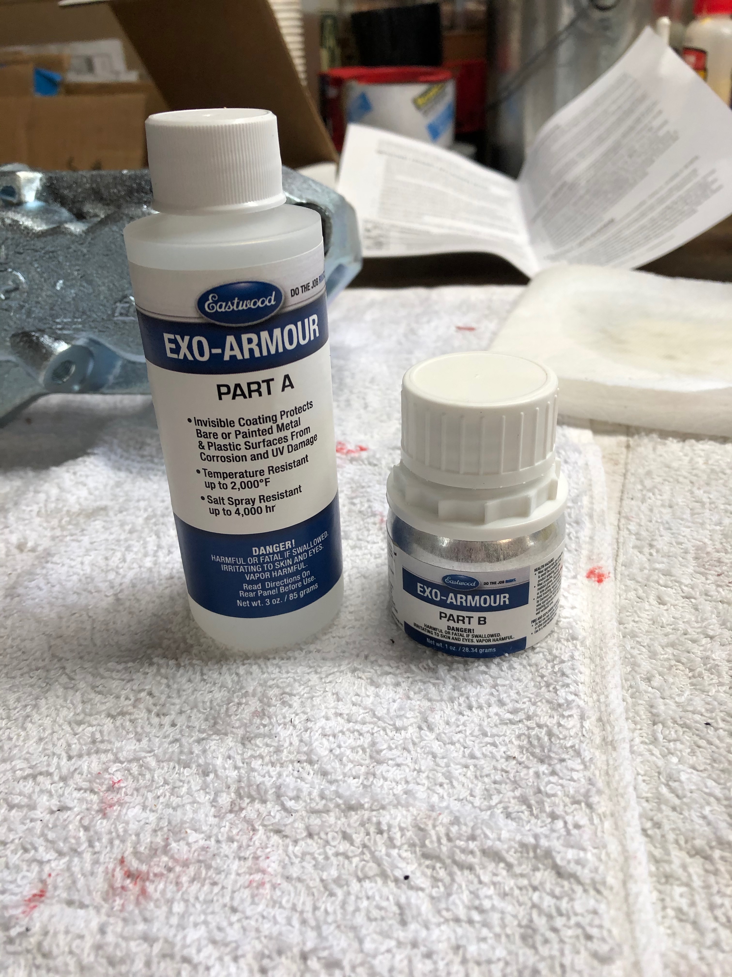
Mixed reviews on that product at Eastwood's own site, but I figured I'd give it a try. I did two coats (a little goes a looooong way), and then "baked" them in an impromptu "oven" (really just a heavy-duty moving box laying on its side with parts suspending inside and a space heater blowing for 4 hours; per IR thermometer, parts were at ~130 deg F for 4 hrs). Final result felt clean & clear, and my hope is that I'll now be able to clean them up easier.
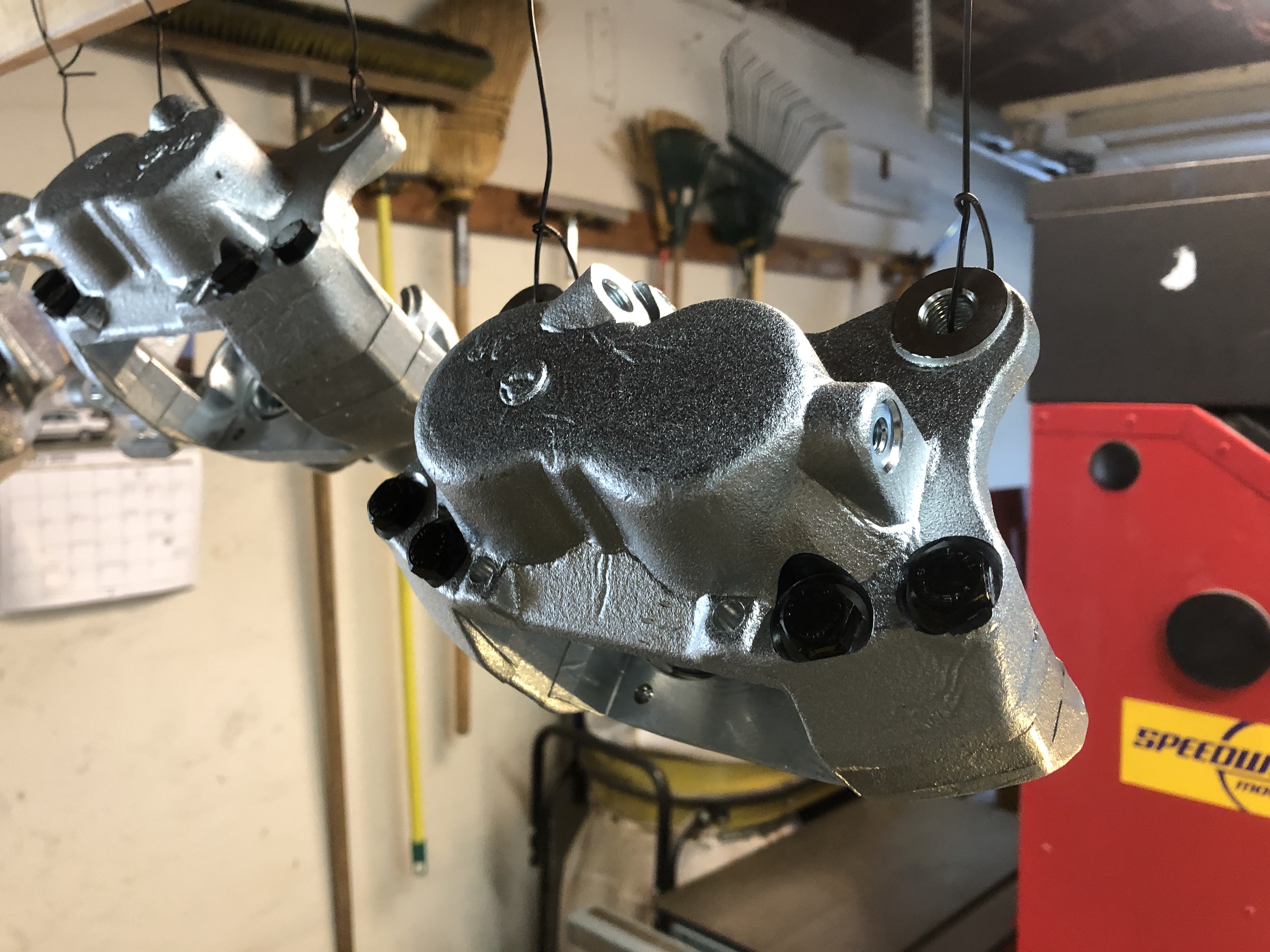
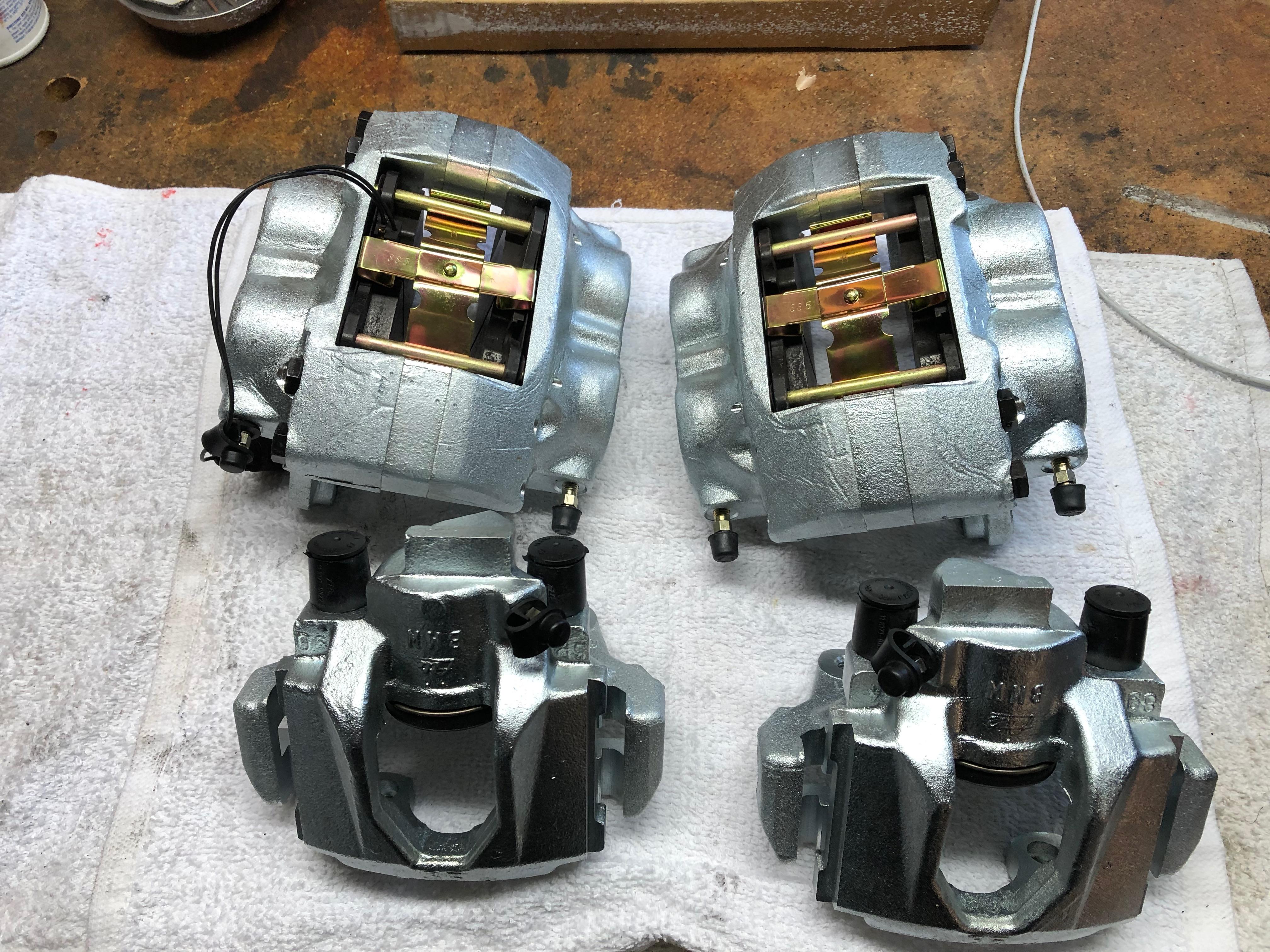
The only thing I forgot (a day late, a part short - fuck), is that I didn't add the rear pad clips to my cad box for replating. So those will have to wait.
I also got a set of Spiegler stainless brake lines for the E34 From Angry Ass. I can post a pic of folks are interested, but I like them because they have black plastic sheathing (closer to stock) and the end fittings spin, so mounting them in the car will be easier.
Next up: I got the weird M10 "penta" bolts back from plating, so the ABS pump went back together too.
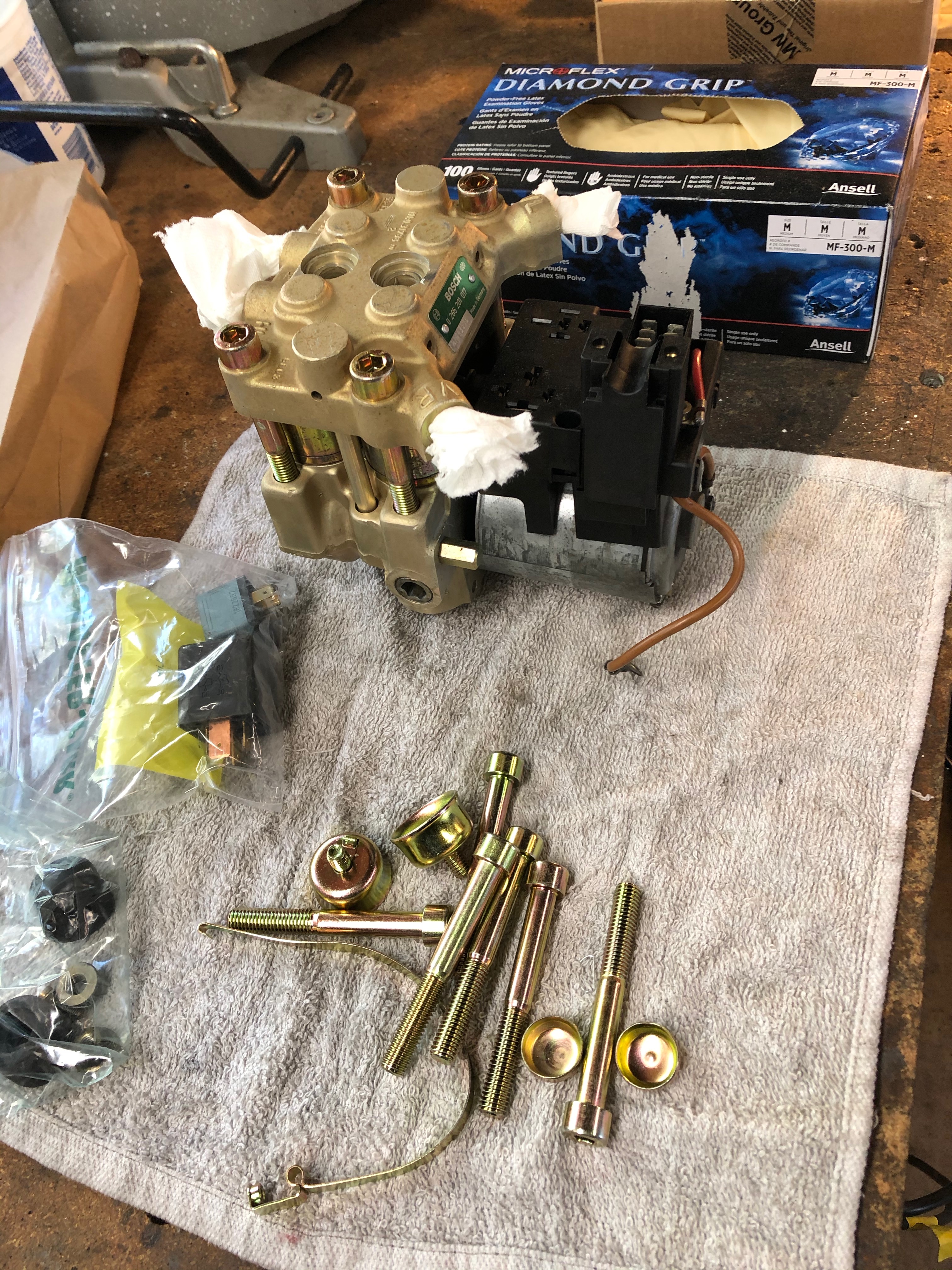
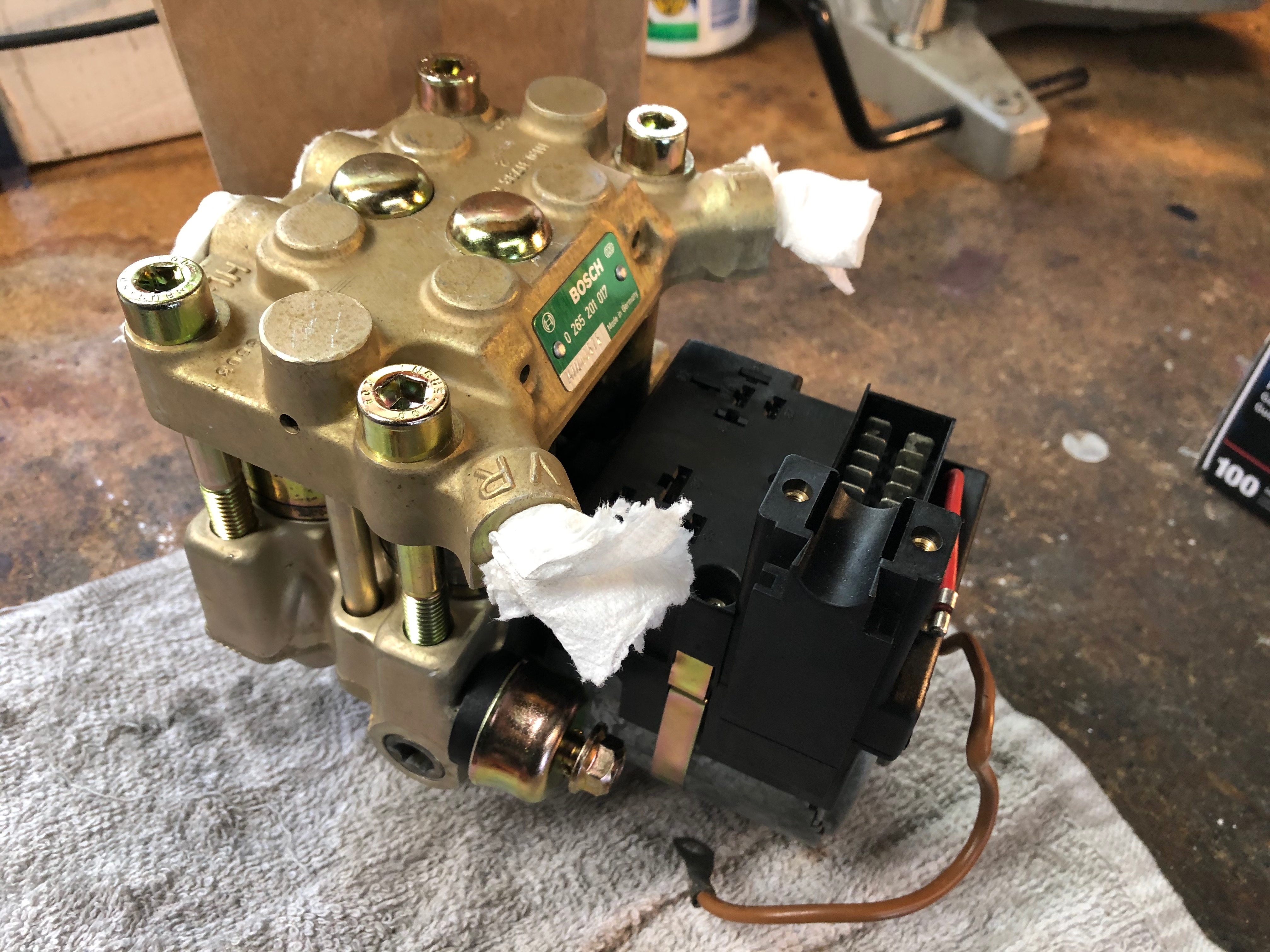
I used this post as a guide on how to disassemble & reassemble the ABS pump[/url]. I came up with a different way to remove those caps on the two penta-bolts in the center, and I also got those caps replated.
The thought occurred to me that things feel like they're progressing well ... except for the bodywork. I hate bodywork.
Until this weekend, that is. With freshly replated M9 bolts (black oxide at Arrow Plating), I had everything in hand to rebuild the brake calipers. The one thing that was bugging me was that in my limited experience, clear zinc plating can sometimes be tough to clean. But I didn't want to try to get these calipers powder coated (either color or clear) cause time & $$$, so after research I found this stuff at Eastwood: two-part, high temp clear coat.

Mixed reviews on that product at Eastwood's own site, but I figured I'd give it a try. I did two coats (a little goes a looooong way), and then "baked" them in an impromptu "oven" (really just a heavy-duty moving box laying on its side with parts suspending inside and a space heater blowing for 4 hours; per IR thermometer, parts were at ~130 deg F for 4 hrs). Final result felt clean & clear, and my hope is that I'll now be able to clean them up easier.


The only thing I forgot (a day late, a part short - fuck), is that I didn't add the rear pad clips to my cad box for replating. So those will have to wait.
I also got a set of Spiegler stainless brake lines for the E34 From Angry Ass. I can post a pic of folks are interested, but I like them because they have black plastic sheathing (closer to stock) and the end fittings spin, so mounting them in the car will be easier.
Next up: I got the weird M10 "penta" bolts back from plating, so the ABS pump went back together too.


I used this post as a guide on how to disassemble & reassemble the ABS pump[/url]. I came up with a different way to remove those caps on the two penta-bolts in the center, and I also got those caps replated.
The thought occurred to me that things feel like they're progressing well ... except for the bodywork. I hate bodywork.
Last edited by jhh925 on Mar 03, 2020 10:31 PM, edited 1 time in total.
Re: Rebuilding My 1988 US-spec M5
That is good to know that the E24 foam fits. Always prefer to use OEM parts wherever possible.jhh925 wrote:Thanks and good to know. I'll check that out. I'd actually already bought the foam pad for the E24 (I think it was P/N 71111113754). I'd been told that it's a *very* close match, but when I held the new E24 pad up to the old one that's in the car, it looks identical - same color, shape, holes, etc.Ordnator wrote:Hi,
There is a gentlemen in Suffolk / Norfolk (UK) who makes up replacement foam pads that fit between the tool tray and the boot lid (large and small) as they are NLA from the main stealers:
https://www.ebay.co.uk/itm/BMW-E30-316- ... Sw3fZcWliz
I have had two of his E28 large tool box foam inserts and found then to be a good replacement option.
I recommend his product without reservation.
Regards,
Mick
Regards,
Mick
Re: Rebuilding My 1988 US-spec M5
Made some progress this weekend by knocking out a couple things that I've been avoiding for a while.
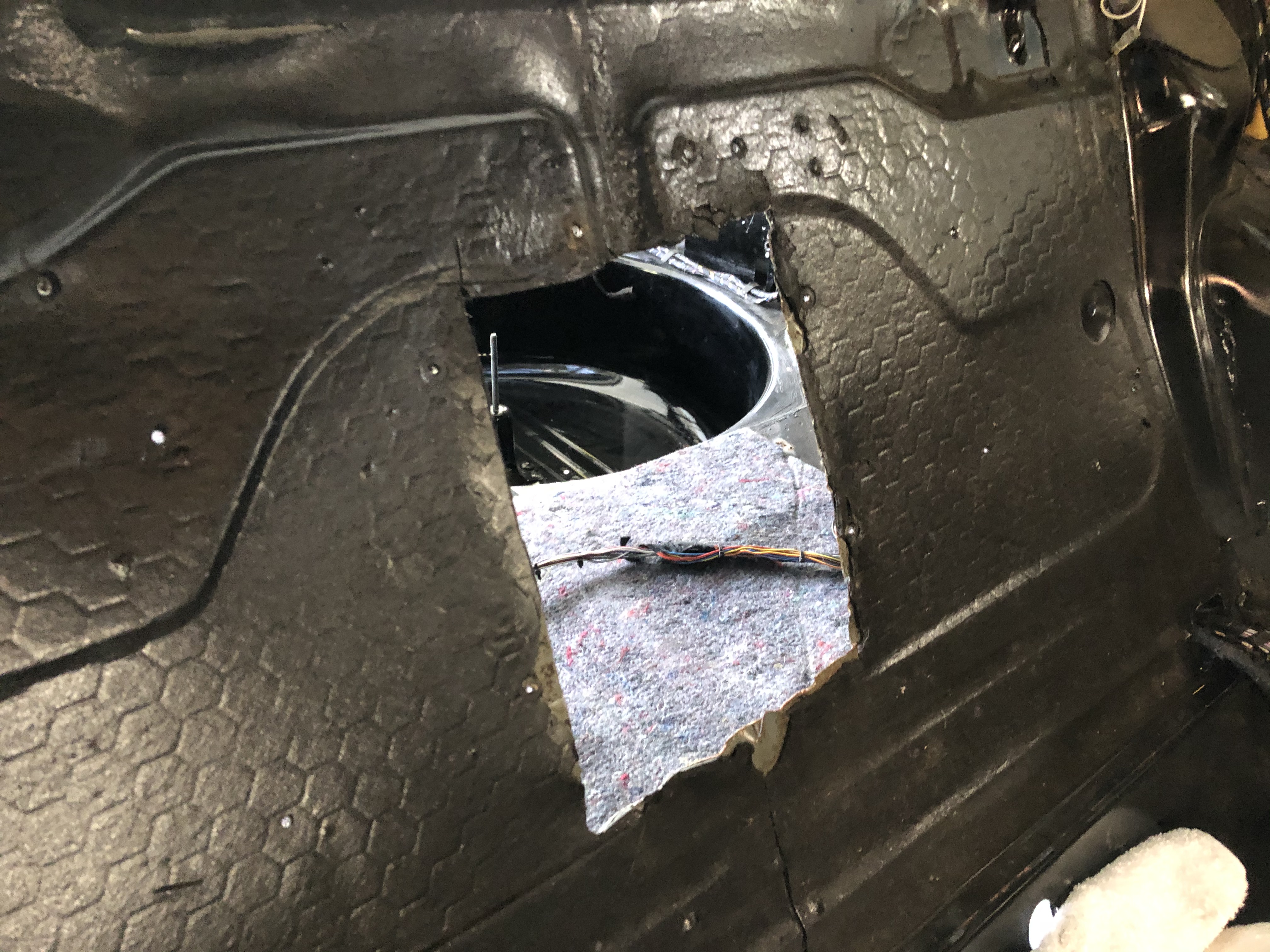
First, I tackled the hole in the rear bulkhead. I figured this would be a good way to hone some sheet metal welding skills by working on a section that's easy access / low visibility.
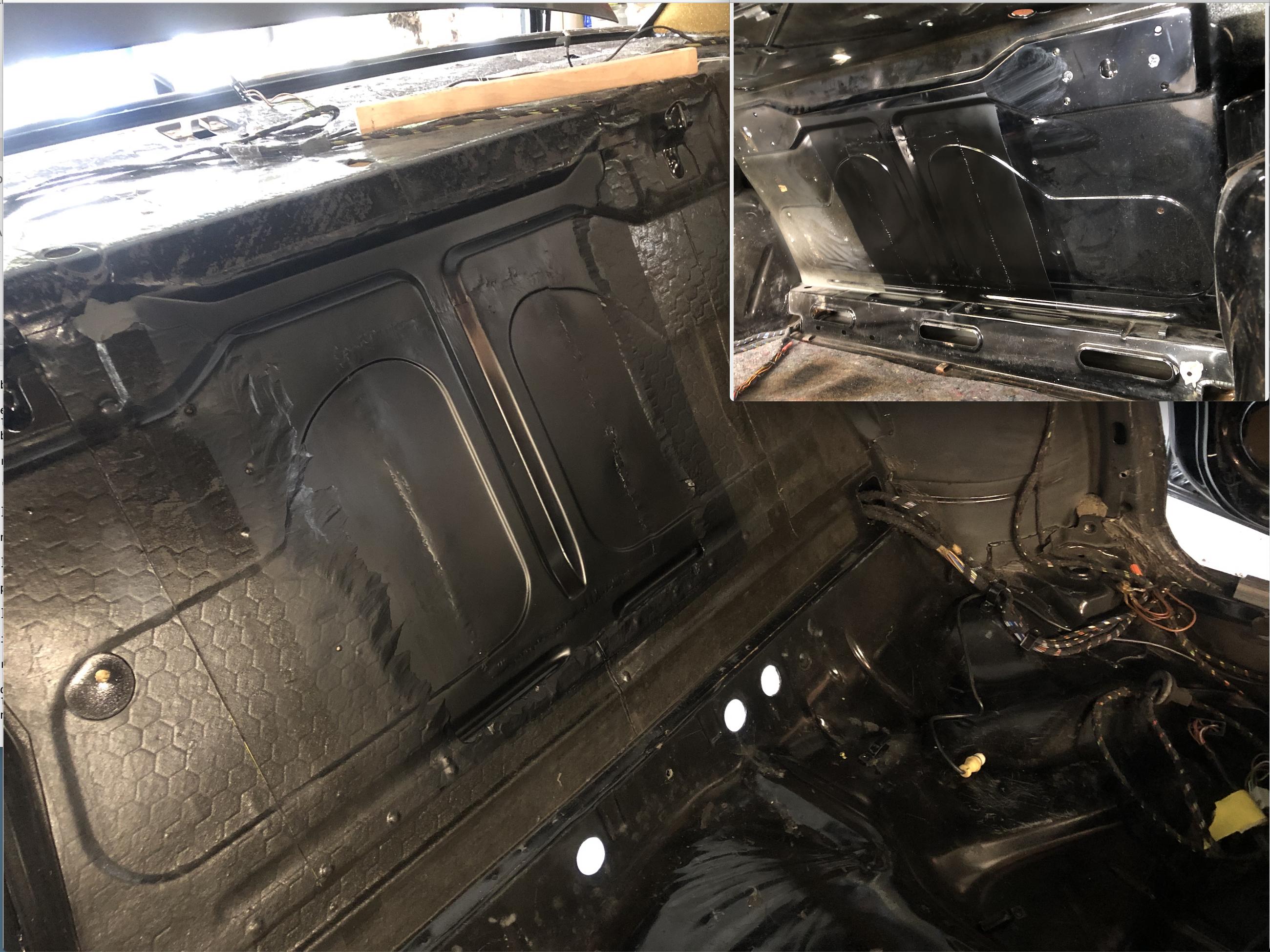
Process was pretty straight forward: Clean up the hole in the bulkhead, straighten the metal edges with a bit of planishing (not only did some PO cut the hole, but they bent up the bulkhead trying to rip the part out), mark the replacement metal, cut it, weld on a stud to make it easier to pull & hold the replacement, clamp the new section in, weld it up from both sides, grind the weld seams down, paint it with black primer.
Here's the before pic:
Cleaned up the hole:
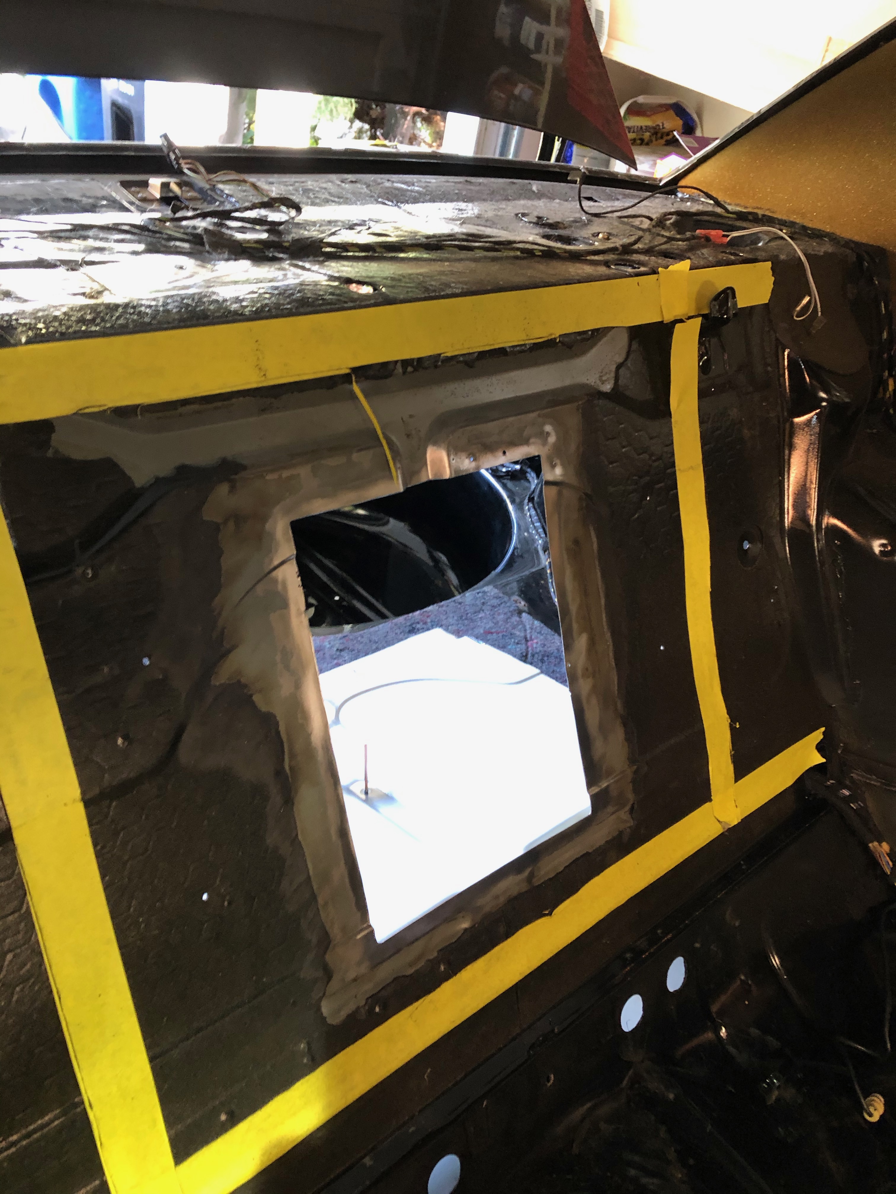
Clamped in and tacked the replacement section:
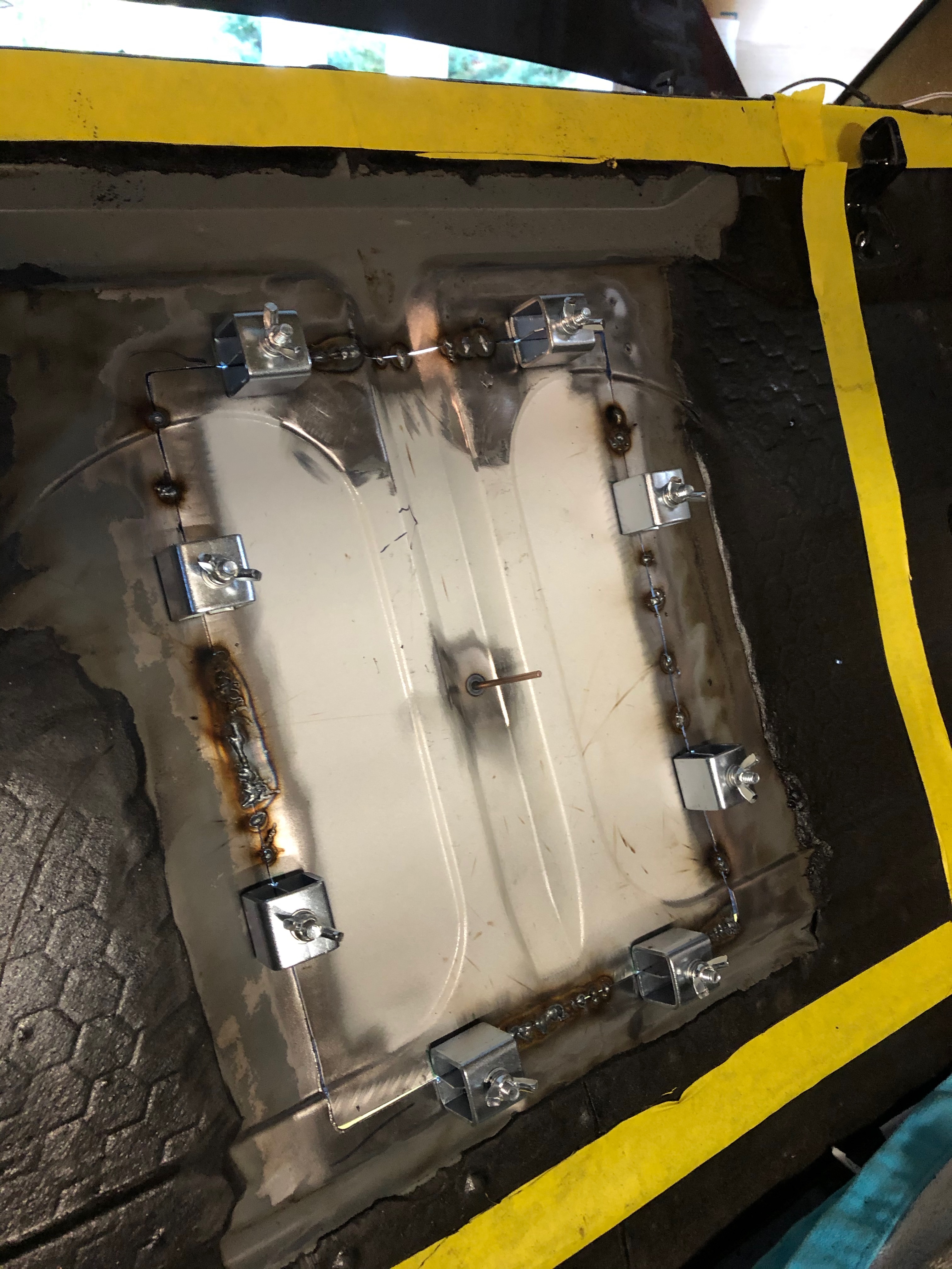
Welding & Grinding done:
After pic, front & back. This will eventually be covered with sound-deadening film on both sides:
I hadn't appreciated beforehand how the trunk-side of the bulkhead is basically just a bit of black overspray on gray primer. I'll probably be spending a bit more time in the trunk cleaning up the battery box, so this will probably get taken care of later.
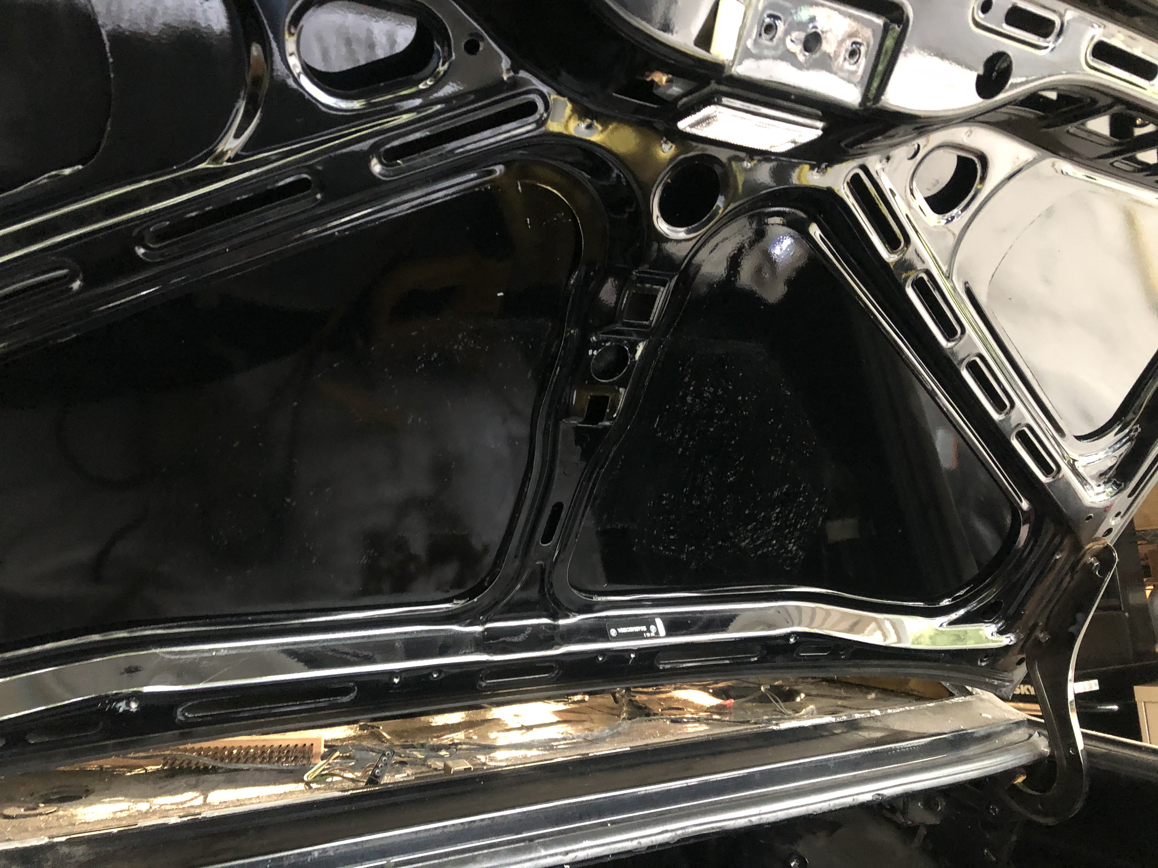
I also tacked the cleanup of the foam tool-kit pad. I figured a heat gun would make quick work of the remainder of the 32-year-old foam. Nope. Heatgun barely softened up. It took at least two hours of gently working the old sticker off with heat, a plastic trim tool, paste wax and adhesive remover. It's hard to see in this pic, but there's still old sticker on this paint. This is about as far as I figure I can take it without risking damage to the pain.
First, I tackled the hole in the rear bulkhead. I figured this would be a good way to hone some sheet metal welding skills by working on a section that's easy access / low visibility.
Process was pretty straight forward: Clean up the hole in the bulkhead, straighten the metal edges with a bit of planishing (not only did some PO cut the hole, but they bent up the bulkhead trying to rip the part out), mark the replacement metal, cut it, weld on a stud to make it easier to pull & hold the replacement, clamp the new section in, weld it up from both sides, grind the weld seams down, paint it with black primer.
Here's the before pic:

Cleaned up the hole:

Clamped in and tacked the replacement section:

Welding & Grinding done:
After pic, front & back. This will eventually be covered with sound-deadening film on both sides:
I hadn't appreciated beforehand how the trunk-side of the bulkhead is basically just a bit of black overspray on gray primer. I'll probably be spending a bit more time in the trunk cleaning up the battery box, so this will probably get taken care of later.

I also tacked the cleanup of the foam tool-kit pad. I figured a heat gun would make quick work of the remainder of the 32-year-old foam. Nope. Heatgun barely softened up. It took at least two hours of gently working the old sticker off with heat, a plastic trim tool, paste wax and adhesive remover. It's hard to see in this pic, but there's still old sticker on this paint. This is about as far as I figure I can take it without risking damage to the pain.

Re: Rebuilding My 1988 US-spec M5
Damn, Jens, do you want to repair my buklhead? With results like that I'm willing to deliver my car to your garage.
Nice work; I want to pick your brain about a few things next weekend.
Nice work; I want to pick your brain about a few things next weekend.
-
Sapotorito
- Posts: 323
- Joined: Apr 18, 2014 10:31 AM
- Location: Chandler, Arizona
Re: Rebuilding My 1988 US-spec M5
I liked what you did to your calipers, thanks for the tip... lots of great stuff here. Subscribed!
Re: Rebuilding My 1988 US-spec M5
I went back to EPS to drop off more parts (EPS did the calipers, Arrow did pretty much everything else) ... "Sorry, we're having to replace our zinc line. No zinc of any kind for a few months."Sapotorito wrote:I liked what you did to your calipers, thanks for the tip... lots of great stuff here. Subscribed!
Re: Rebuilding My 1988 US-spec M5
Can't wait! And after we all get quarantined at Darin's house, we should have puh-lenty of time.vinceg101 wrote:Damn, Jens, do you want to repair my buklhead? With results like that I'm willing to deliver my car to your garage.
Nice work; I want to pick your brain about a few things next weekend.
And I'm not sure if I said somewhere, but I actually bought a part-out 528e for parts and cut the bulkhead out of that car. It helps a ton to have, essentially, a perfectly pre-formed piece of metal to start with.
Last edited by jhh925 on Mar 13, 2020 11:37 PM, edited 1 time in total.
Re: Rebuilding My 1988 US-spec M5
I see it now: we all will be packed into Darin's house, the CDC will have arrived and taped & plastic covered all the exits, and we will be inside partying like it's 1999 or at least until his booze is gone; then it gets ugly after that.jhh925 wrote:Can't wait! And after we all get quarantined at Darin's house, we should have ph-lenty of time.
Don't I know it, I've been accumulating parts for years: I have floor boards corners, rocker panels @ the jack points, and the rear bulkhead section (an audio installer butchered mine like they did yours).jhh925 wrote:And I'm not sure if I said somewhere, but I actually bought a part-out 528e for parts and cut the bulkhead out of that car. It helps a ton to have, essentially, a perfectly pre-formed piece of metal to start with.
Re: Rebuilding My 1988 US-spec M5
Yeah, let's talk.vinceg101 wrote:I have ... rocker panels @ the jack points ... "
Re: Rebuilding My 1988 US-spec M5
This weekend is the euro conversion on the tail panel. Here's the before:
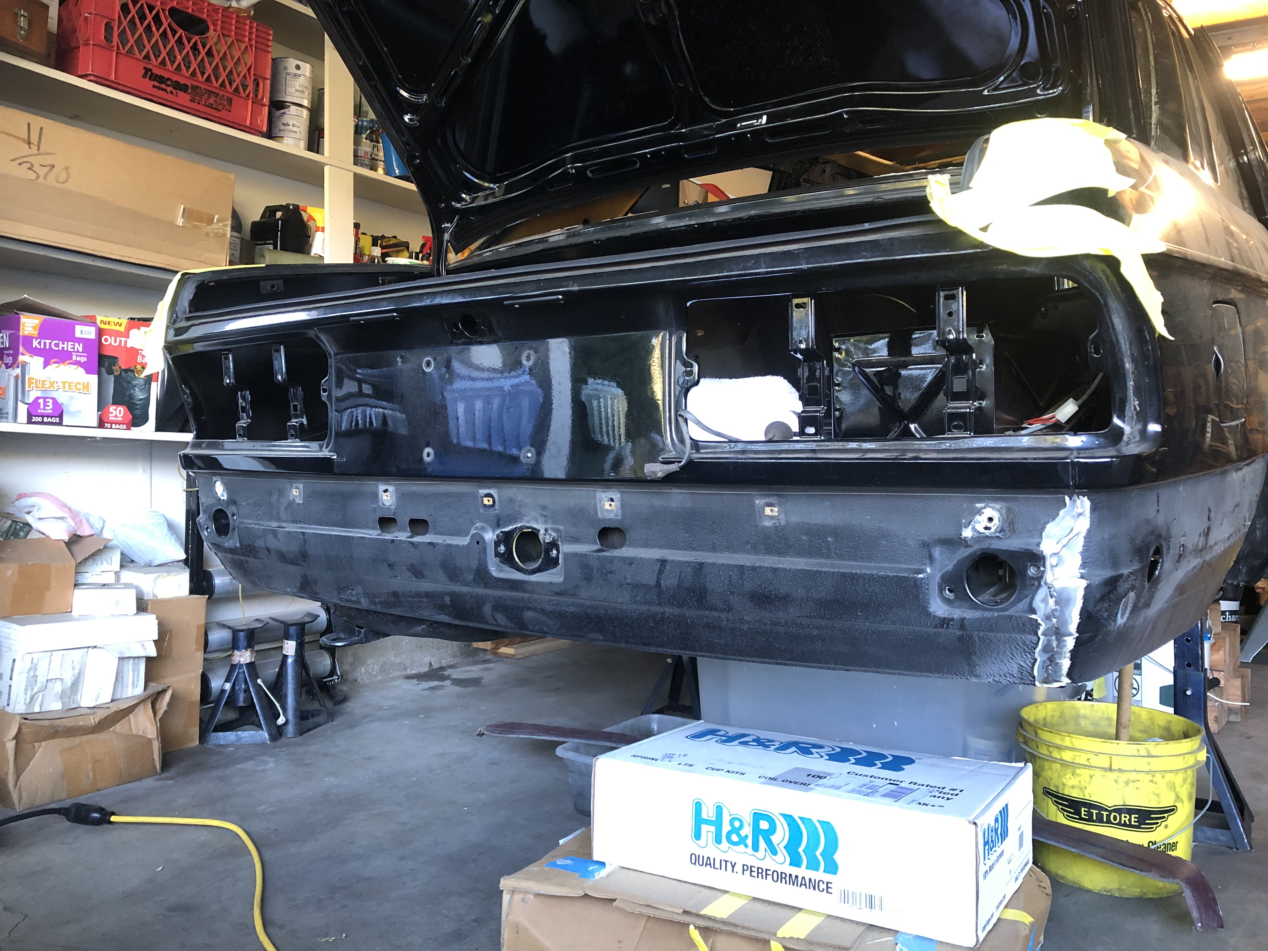
I'd previously sourced a new BMW Euro OEM tail panel (thanks, Ivo). But in comparing the outline of the new euro part to the weld seams (as best I could pick them out under the schutz coating), I couldn't figure out how the new panel was supposed to fit in. Specifically, the line of the new panel didn't come close to matching the weld seams at the lower quarter panels.
After poking around and asking a few people who had been-there-done-that, I learned that the euro tail panel slipped in behind the rear quarter ... so the weld seam occurred where the lower rear quarter essentially wrapped around the tail panel. A pic is better to show what I'm talking about. The dashed red line is where the tail panel slips underneath the rear quarter:
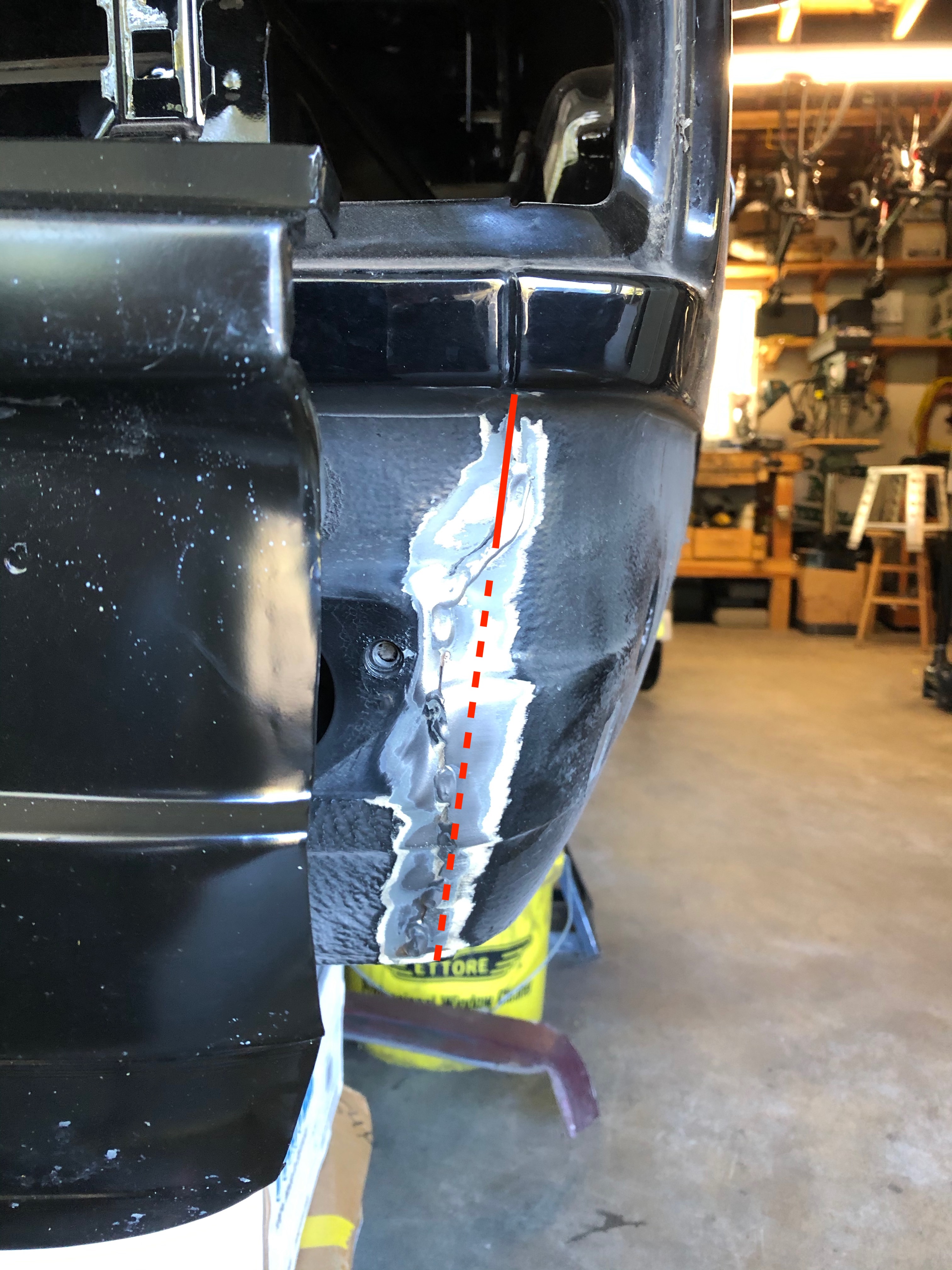
(One of my other take-aways here is that the original factory welding between tail panel & rear quarter wasn't that neat to begin with, and they used the schutz to cover a lot of quick work - so my weld-n-grind style should work out OK.)
So, with that info in hand, I decided that I would not try to replace the entire tail panel. Instead, I'd cut the existing tail panel horizontally in the area under the bumper, remove all the old US tail panel from that cut line down, then cut the new tail panel to match, & weld it all in. Simple.
Here's progress so far. In order to make it as easy as possible to match the cut lines, I used this homemade jig to guide the cutting wheel.
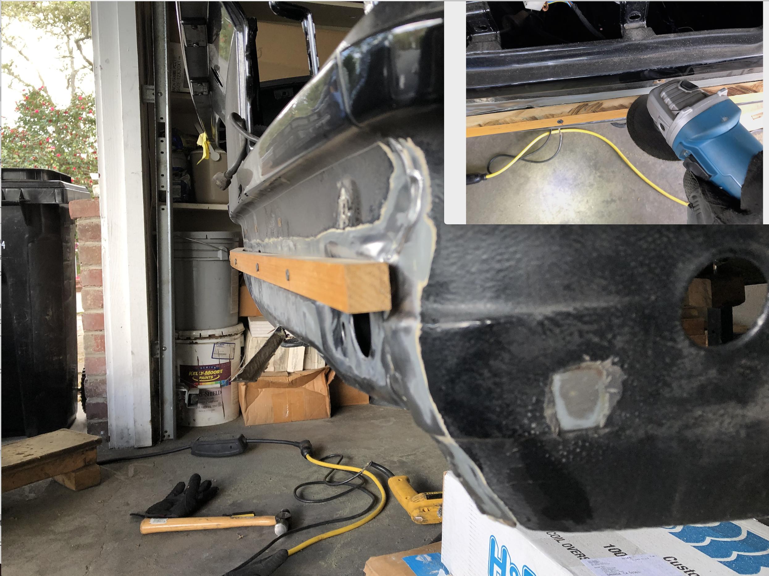
Results were good ...
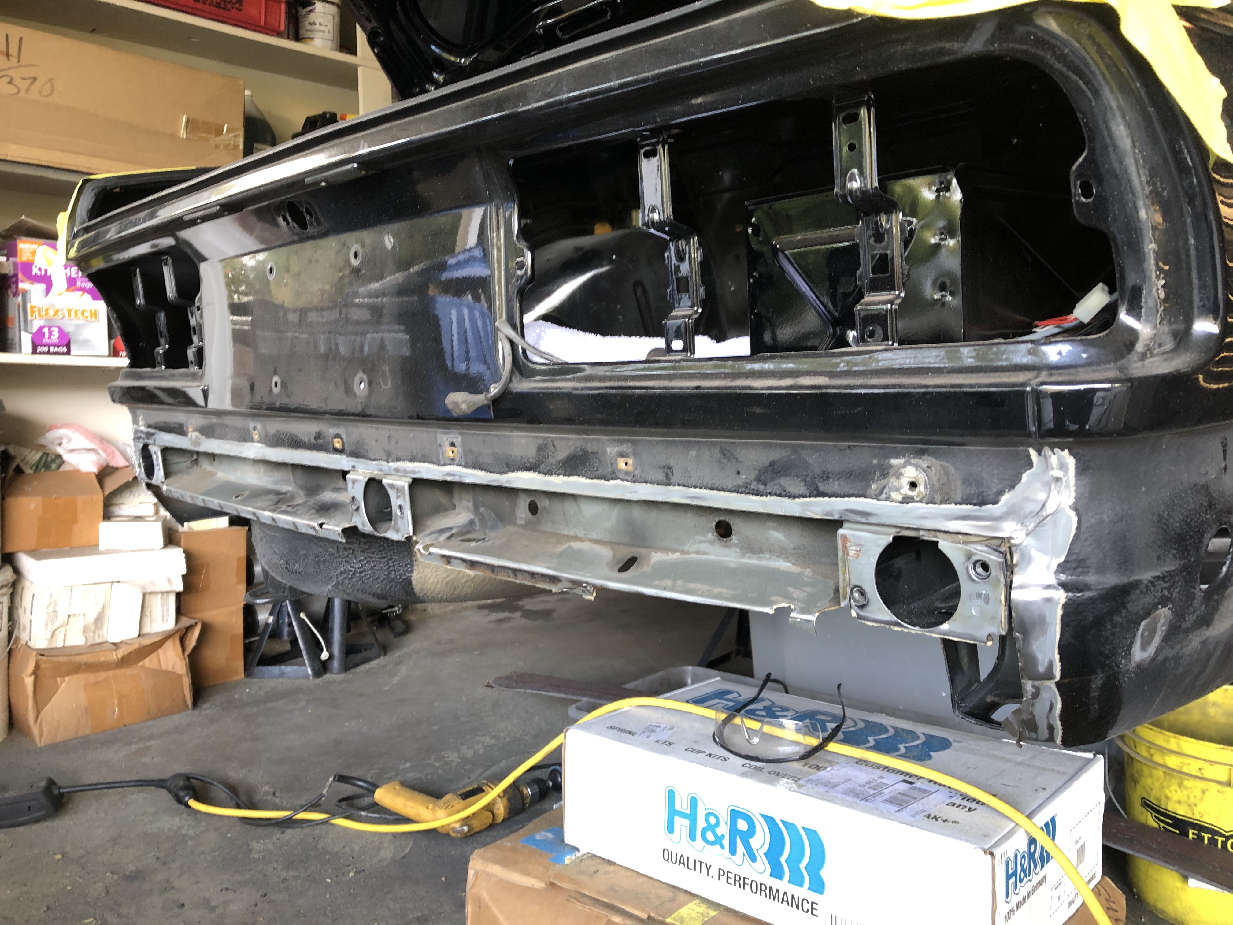
... though if you have an eagle-eye you'll see that I cut too high in the lower section and cut into the spot-weld seam of the "C" channel part at the bottom. As I write this, I've already repaired that, and I'll add pics tomorrow after I get back in the garage.
And here's the remainder section of the old tail panel that I've pried out from behind the rear quarter. Getting this whole thing out all the way up to the horizontal cut line will be tricky.
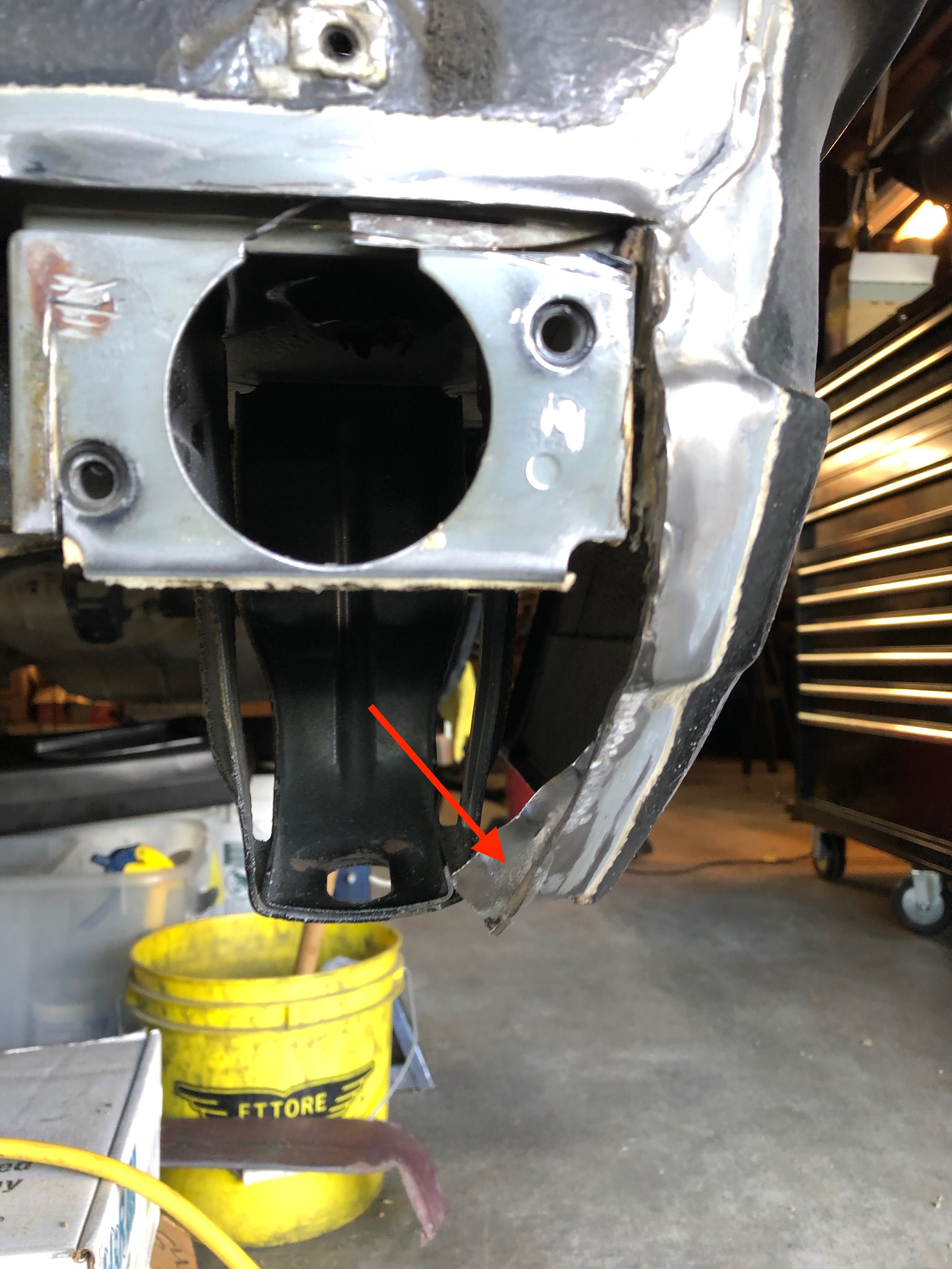
I'm cautiously optimistic that this rear tail panel conversion will go well.
(And I need a bigger frikkin garage. Damn.)

I'd previously sourced a new BMW Euro OEM tail panel (thanks, Ivo). But in comparing the outline of the new euro part to the weld seams (as best I could pick them out under the schutz coating), I couldn't figure out how the new panel was supposed to fit in. Specifically, the line of the new panel didn't come close to matching the weld seams at the lower quarter panels.
After poking around and asking a few people who had been-there-done-that, I learned that the euro tail panel slipped in behind the rear quarter ... so the weld seam occurred where the lower rear quarter essentially wrapped around the tail panel. A pic is better to show what I'm talking about. The dashed red line is where the tail panel slips underneath the rear quarter:

(One of my other take-aways here is that the original factory welding between tail panel & rear quarter wasn't that neat to begin with, and they used the schutz to cover a lot of quick work - so my weld-n-grind style should work out OK.)
So, with that info in hand, I decided that I would not try to replace the entire tail panel. Instead, I'd cut the existing tail panel horizontally in the area under the bumper, remove all the old US tail panel from that cut line down, then cut the new tail panel to match, & weld it all in. Simple.
Here's progress so far. In order to make it as easy as possible to match the cut lines, I used this homemade jig to guide the cutting wheel.

Results were good ...

... though if you have an eagle-eye you'll see that I cut too high in the lower section and cut into the spot-weld seam of the "C" channel part at the bottom. As I write this, I've already repaired that, and I'll add pics tomorrow after I get back in the garage.
And here's the remainder section of the old tail panel that I've pried out from behind the rear quarter. Getting this whole thing out all the way up to the horizontal cut line will be tricky.

I'm cautiously optimistic that this rear tail panel conversion will go well.
(And I need a bigger frikkin garage. Damn.)
Re: Rebuilding My 1988 US-spec M5
Progress on Euro tail panel is delayed due to sheltering in place - need stuff from the HW store and I haven't been able to get down there yet during the "sheltering in place."
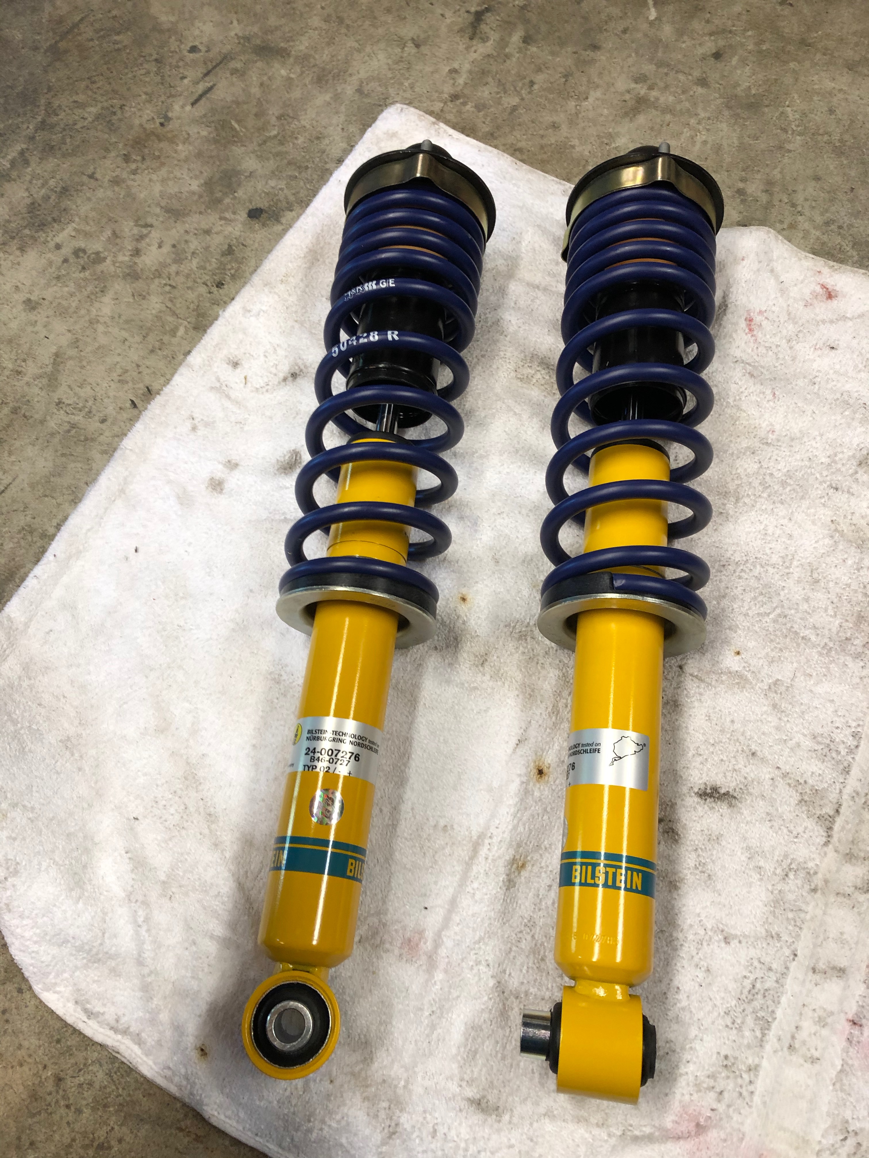
Meanwhile, though, the "do I delete the SLS" question has been answered:
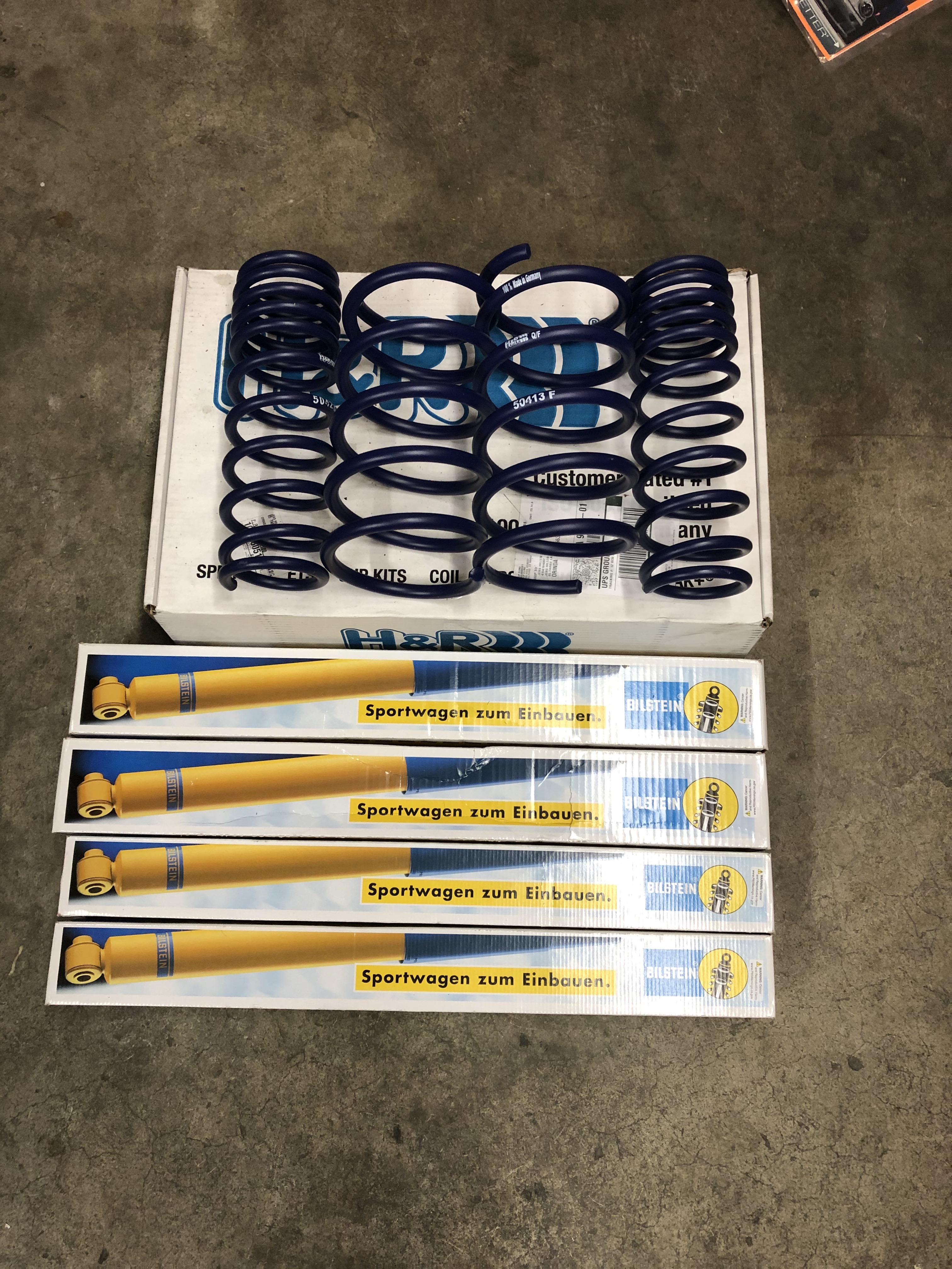
H&R Sport 50428, Bilstein B8 Sports (24-007276 rear, 34-181546 front).
Meanwhile, though, the "do I delete the SLS" question has been answered:

H&R Sport 50428, Bilstein B8 Sports (24-007276 rear, 34-181546 front).
-
Nebraska_e28
- Beamter

- Posts: 9058
- Joined: Apr 13, 2006 11:18 PM
- Location: Council Bluffs, IA
- Contact:
Re: Rebuilding My 1988 US-spec M5
Great story! Subscribed for updates.
Re: Rebuilding My 1988 US-spec M5
Juuuust about done on the euro tail panel installation. More to come on that, but I'm very happy how it's turning out.
Meantime, I received the throttle plate repair kit from Moosehead Engineering (thanks, Paul!), installed it and got the initial adjustments done on the butterfly and throttle linkages.
I started with what I believe is a factory shop document that outlines the ITB adjustments, but has a method intended to be used with a single dial indicator that's mounted to spots on the head & throttles with what I presume is a BMW-specific tool. Well, this is MyE28 ... we don't use the right tool when you have three of four wrong ones that can do the job just as well!
Here's the setup I used; all the dial indicators were cheap chinesium (~$15 each) and I made the indicator plates myself out of scrap wood.
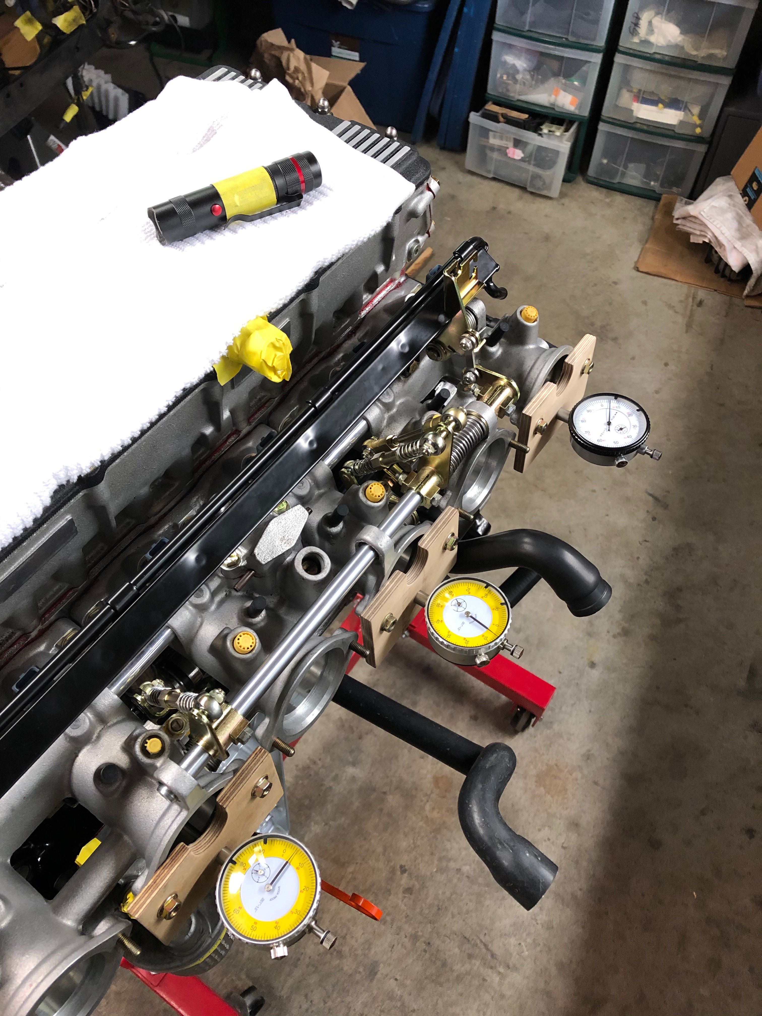
Here's the method I followed:
1. Started with all three link bars detached.
2. Set a dial indicator on each ITB. Zeroed each out.
3. Independently set each ITB stop screw so that the bottom of the butterfly valve was open by +.005" from zero (specs are to set it between 0.10 and 0.15mm = 0.004 to 0.006")
4. Left each dial indicator in place.
5. Attached first link bar (for cyls 5+6).
6. Adjusted the length of that bar so that when butterfly valve & throttle cable plate were both at rest, the dial indicator read +.005"
7. Next, attached the second link bar (cyls 3+4).
8. Adjusted that link bar so that when all was at rest, both dial indicators (for 3+4 and 5+6) read +0.005"
9. Next, attached the third link bar (cyls 1+2).
8. Adjusted that link bar so that when all was at rest, all three dial indicators (for 1+2, 3+4 and 5+6) all read +0.005"
9. Confirmed adjustment by actuating throttle cable plate. All dial indicators consistently came to rest at +0.005"
10. Set the WOT limit screw by using a vernier caliper to hold the #6 butterfly at exactly full open (plate parallel to throttle body axis, so same distance above & below the open butterfly), then adjusting the stop screw to just touch the throttle plate stop.
11. Confirmed WOT limit screw adjustment by opening throttles & measuring the #6 butterfly position. (Took a couple tries to get it right.)
Here's a short vid of the final check.
Meantime, I received the throttle plate repair kit from Moosehead Engineering (thanks, Paul!), installed it and got the initial adjustments done on the butterfly and throttle linkages.
I started with what I believe is a factory shop document that outlines the ITB adjustments, but has a method intended to be used with a single dial indicator that's mounted to spots on the head & throttles with what I presume is a BMW-specific tool. Well, this is MyE28 ... we don't use the right tool when you have three of four wrong ones that can do the job just as well!
Here's the setup I used; all the dial indicators were cheap chinesium (~$15 each) and I made the indicator plates myself out of scrap wood.

Here's the method I followed:
1. Started with all three link bars detached.
2. Set a dial indicator on each ITB. Zeroed each out.
3. Independently set each ITB stop screw so that the bottom of the butterfly valve was open by +.005" from zero (specs are to set it between 0.10 and 0.15mm = 0.004 to 0.006")
4. Left each dial indicator in place.
5. Attached first link bar (for cyls 5+6).
6. Adjusted the length of that bar so that when butterfly valve & throttle cable plate were both at rest, the dial indicator read +.005"
7. Next, attached the second link bar (cyls 3+4).
8. Adjusted that link bar so that when all was at rest, both dial indicators (for 3+4 and 5+6) read +0.005"
9. Next, attached the third link bar (cyls 1+2).
8. Adjusted that link bar so that when all was at rest, all three dial indicators (for 1+2, 3+4 and 5+6) all read +0.005"
9. Confirmed adjustment by actuating throttle cable plate. All dial indicators consistently came to rest at +0.005"
10. Set the WOT limit screw by using a vernier caliper to hold the #6 butterfly at exactly full open (plate parallel to throttle body axis, so same distance above & below the open butterfly), then adjusting the stop screw to just touch the throttle plate stop.
11. Confirmed WOT limit screw adjustment by opening throttles & measuring the #6 butterfly position. (Took a couple tries to get it right.)
Here's a short vid of the final check.
Re: Rebuilding My 1988 US-spec M5
Making plenty of progress while I'm "working" from home. I'm really happy with how the tail panel ended up. Here's after first primer coat & seam sealer:
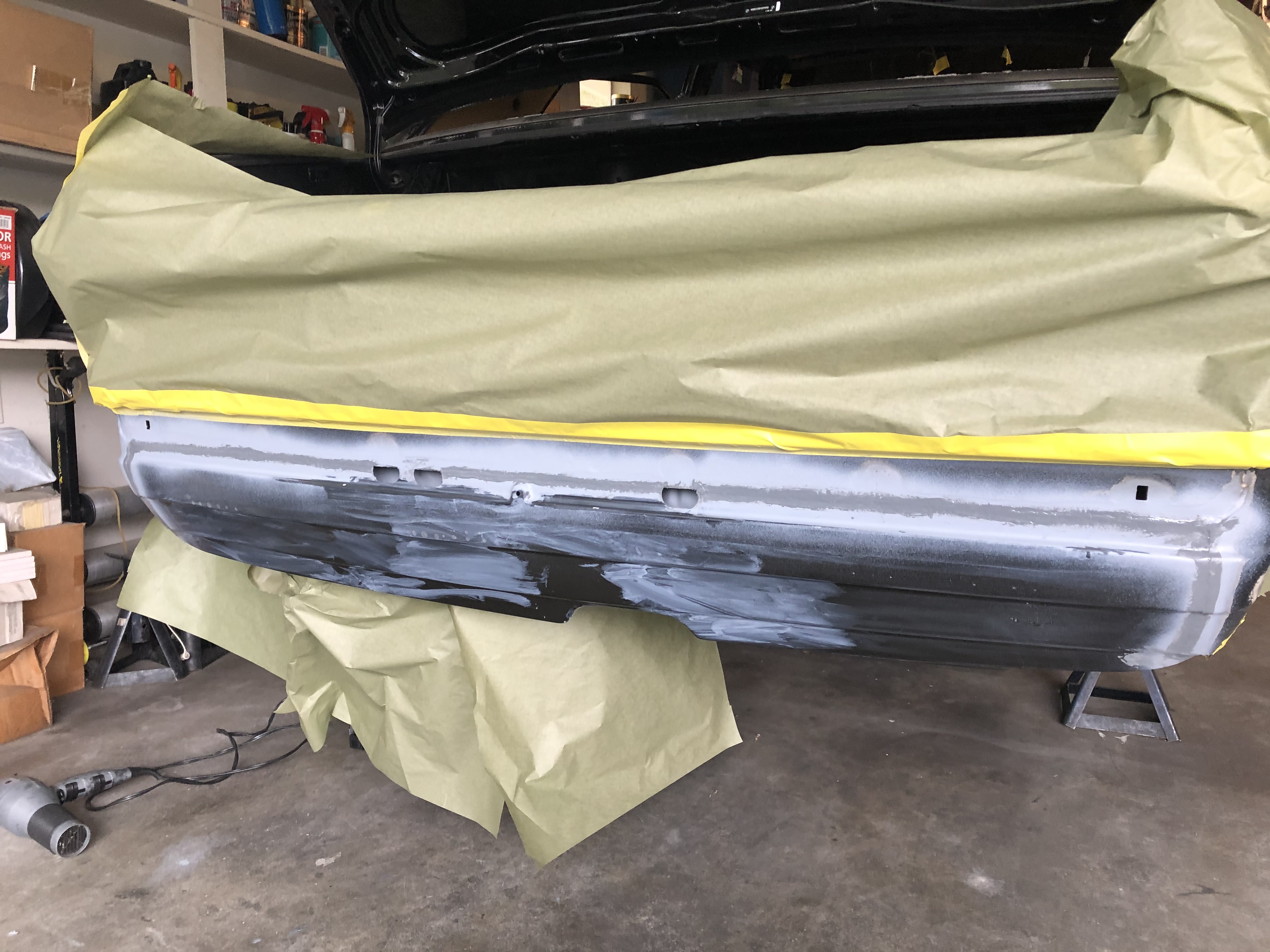
And after a coat of black primer to keep everything clean as the car sits before actually getting painted:
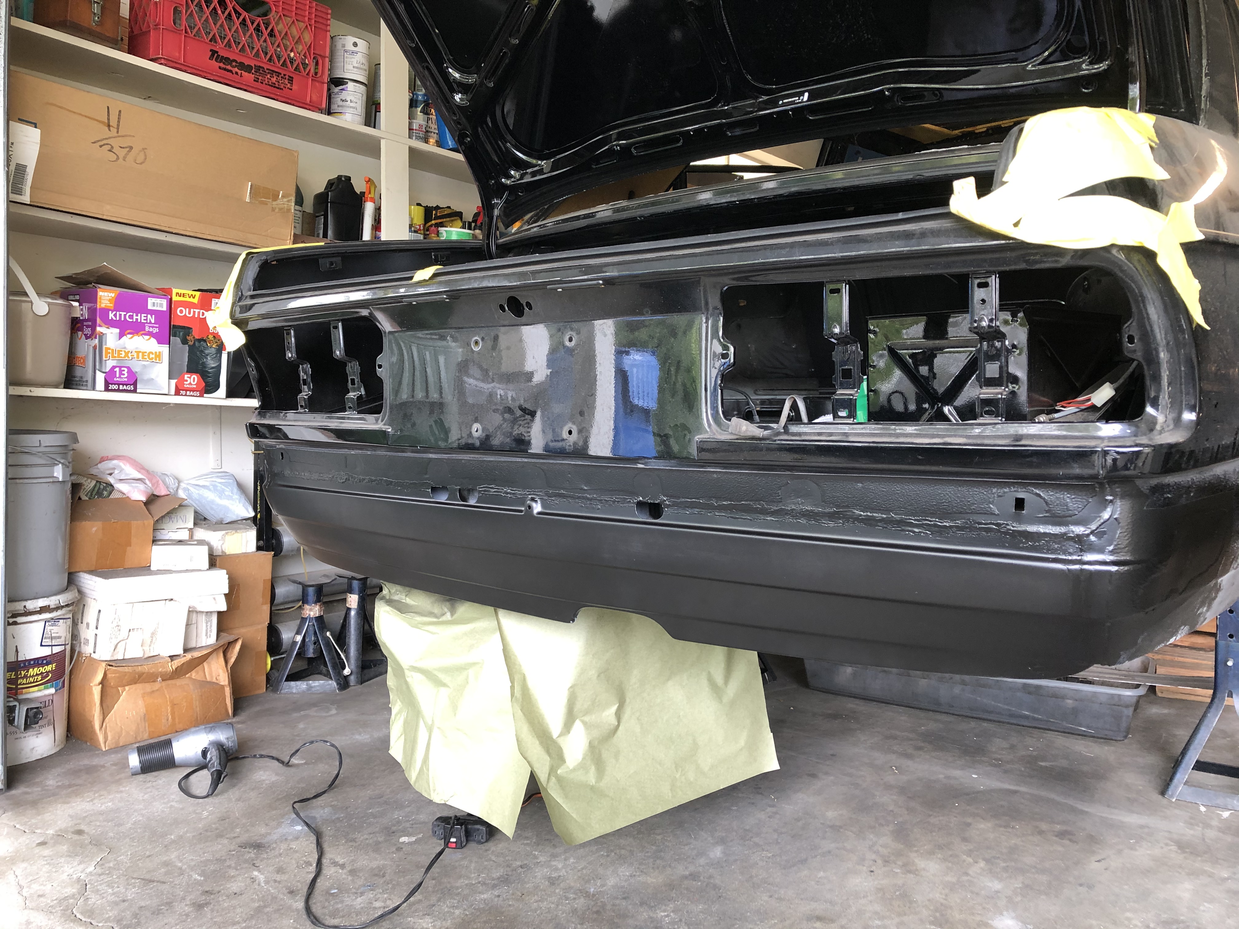
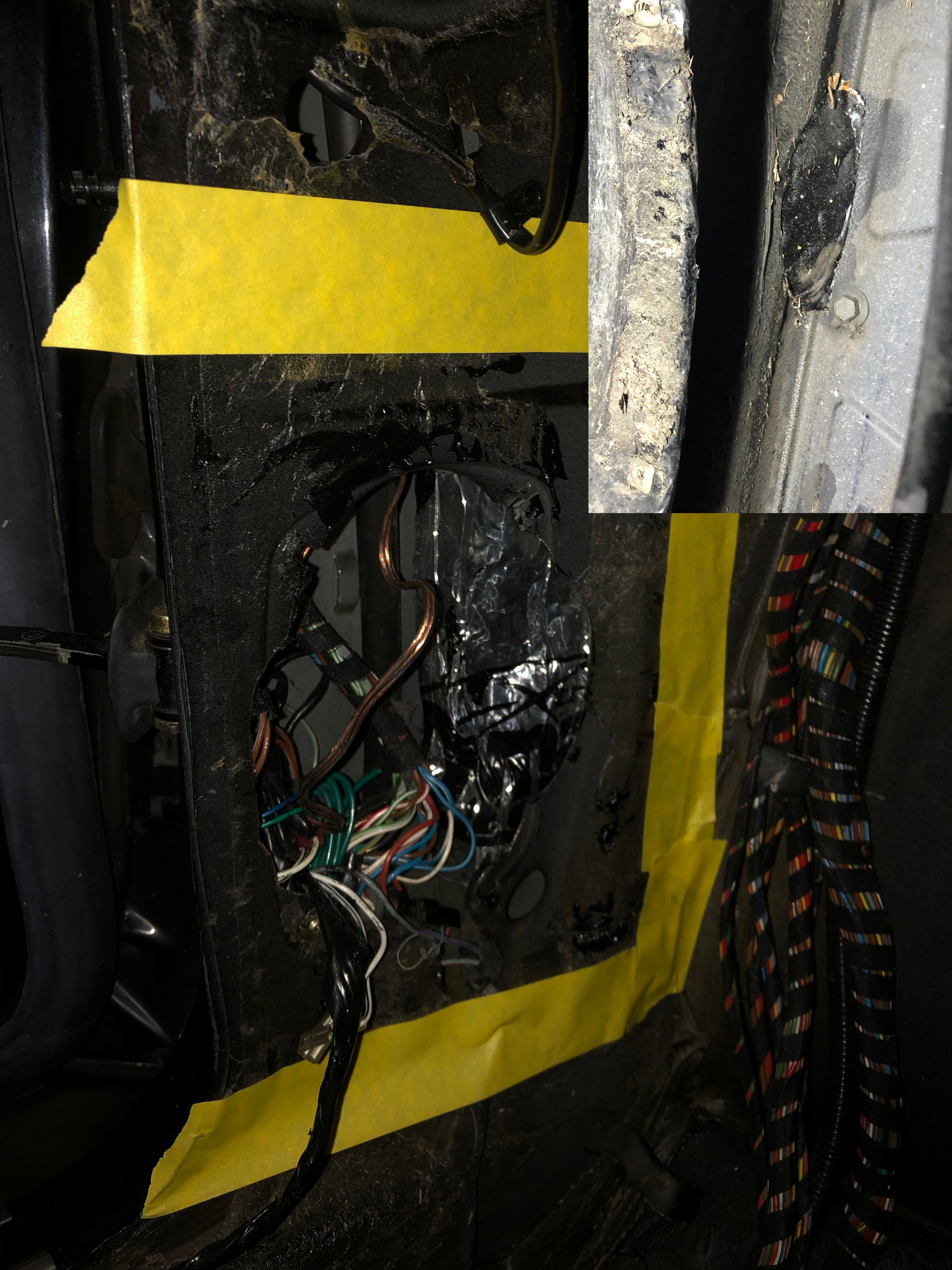
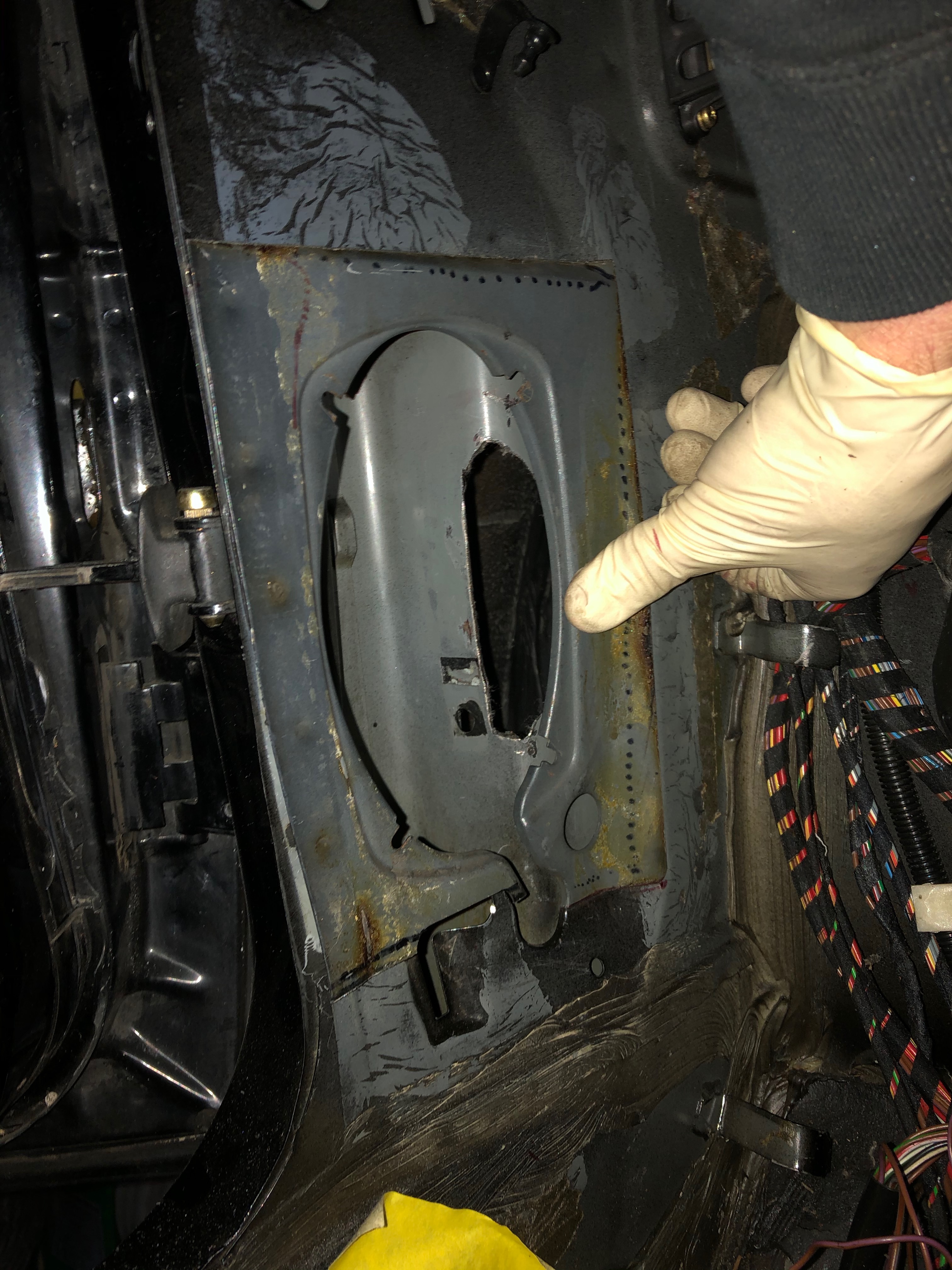
Time to move on to other things! Making good progress as well on correcting the butchery that was inflicted on the driver side foot well speaker panel. Here's what I discovered when I first disassembled the car; the inset is the view from inside the fender well where the stereo installed managed (accidentally? Intentionally?!?) to cut through the frame and into the fender well. (Sorry for the crappy dark pic of the speaker panel ... I'm no pro photog):
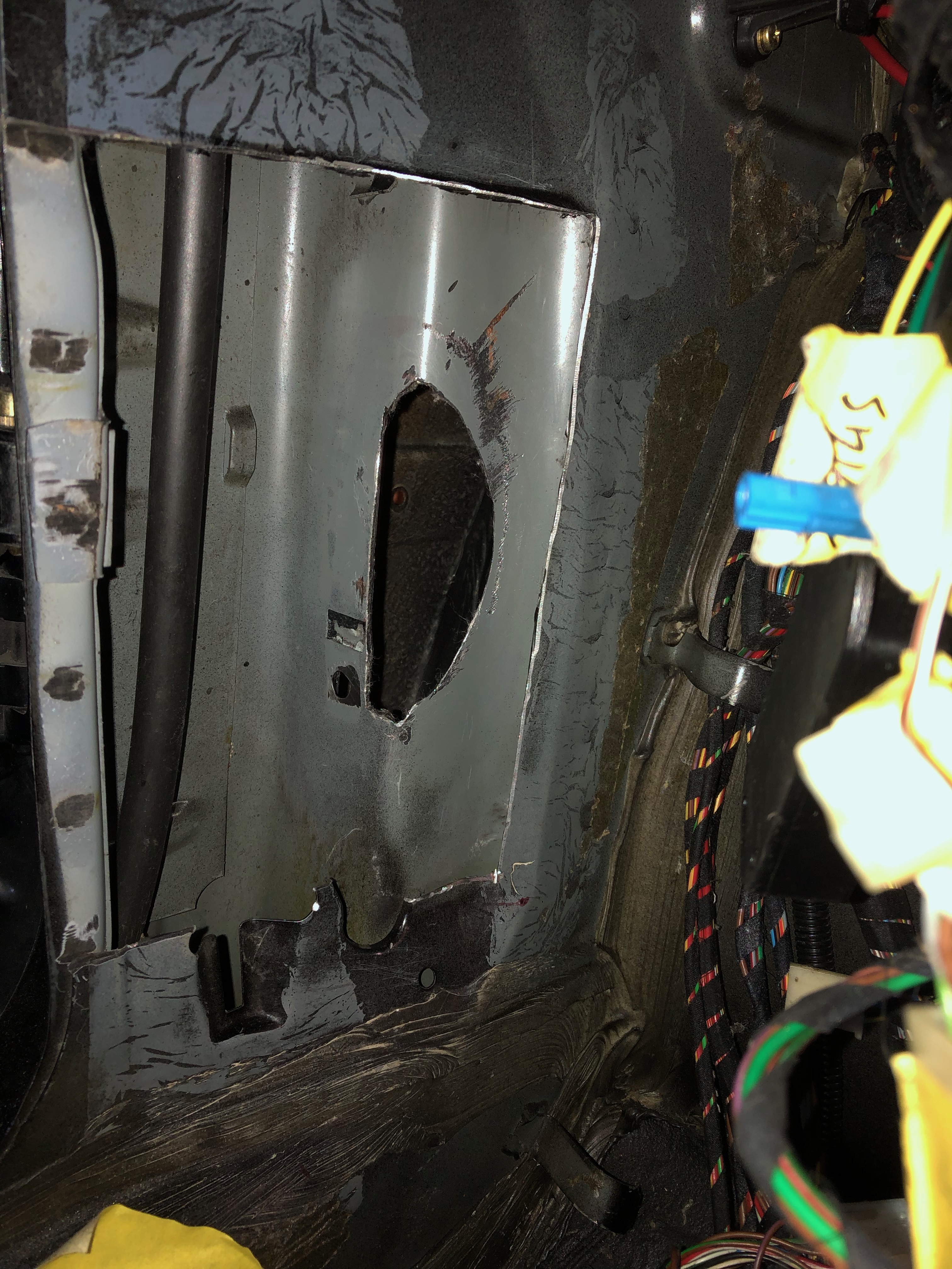
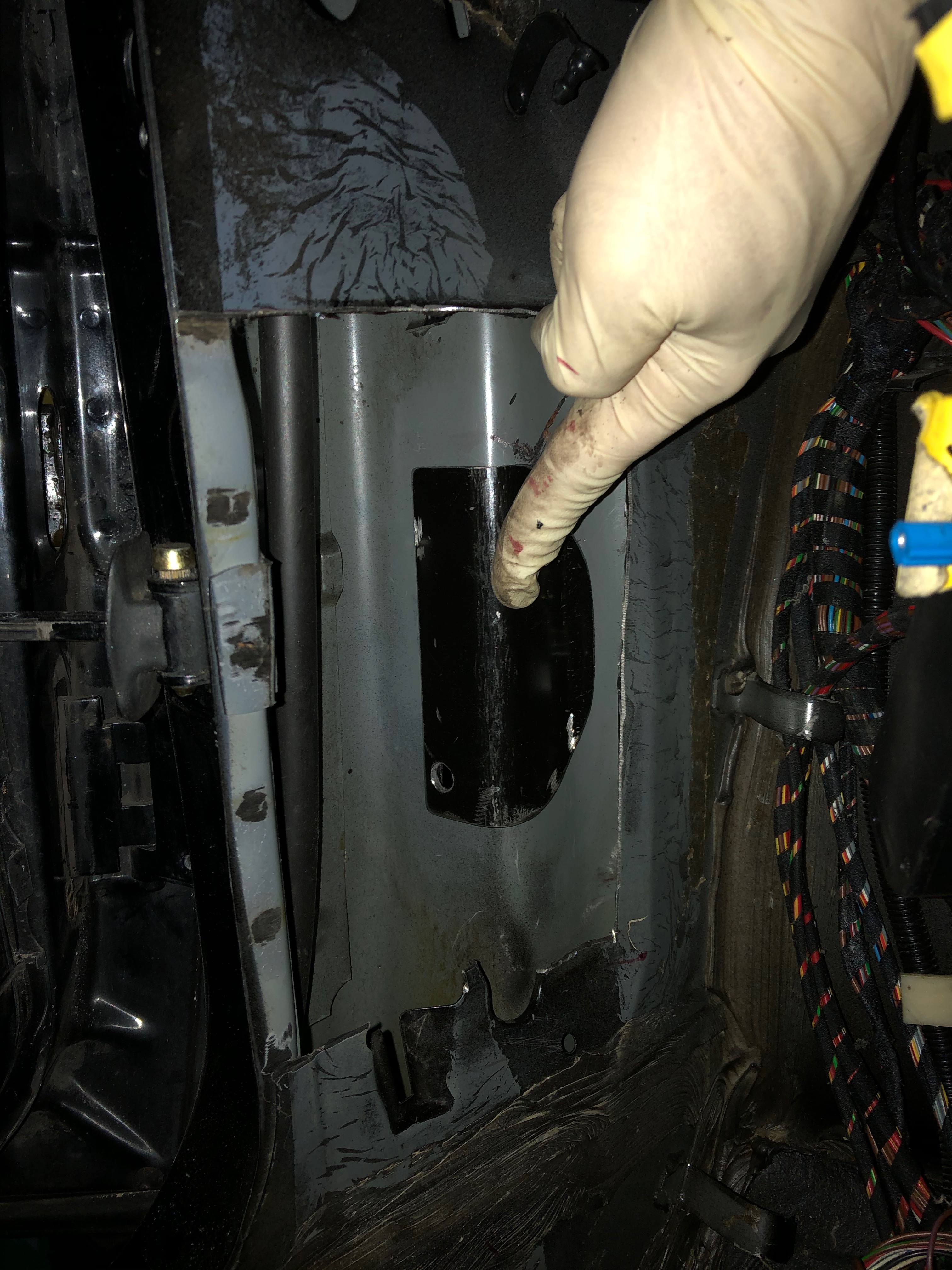
Got a new donor panel from a board member, and also fabricated a patch for the fender well hole. These pics are before final fitting. Hoping to get these welded in sometime this week.
After clean-up:
Hole patch:
Dry-fit of new speaker panel:
One of the original questions I had is whether I should get the whole car re-painted ... The entire lower tail panel will need to get re-shutzed and repainted, along with the lower quarters. I haven't gotten to the front of the car for the euro bumper conversion, but the entire front valance will need to be repainted, along with the small bar under the front grill that has all the small mounting holes for the US bumper trim. There will be other stuff after my work, and none of that includes the small dents & dings that I wanted to get fixed in the first place. All that is telling me I'll probably want to get the whole car painted, which I'm not looking forward to, given how hard it is to find a good shop to get that done.

And after a coat of black primer to keep everything clean as the car sits before actually getting painted:

Time to move on to other things! Making good progress as well on correcting the butchery that was inflicted on the driver side foot well speaker panel. Here's what I discovered when I first disassembled the car; the inset is the view from inside the fender well where the stereo installed managed (accidentally? Intentionally?!?) to cut through the frame and into the fender well. (Sorry for the crappy dark pic of the speaker panel ... I'm no pro photog):

Got a new donor panel from a board member, and also fabricated a patch for the fender well hole. These pics are before final fitting. Hoping to get these welded in sometime this week.
After clean-up:

Hole patch:

Dry-fit of new speaker panel:

One of the original questions I had is whether I should get the whole car re-painted ... The entire lower tail panel will need to get re-shutzed and repainted, along with the lower quarters. I haven't gotten to the front of the car for the euro bumper conversion, but the entire front valance will need to be repainted, along with the small bar under the front grill that has all the small mounting holes for the US bumper trim. There will be other stuff after my work, and none of that includes the small dents & dings that I wanted to get fixed in the first place. All that is telling me I'll probably want to get the whole car painted, which I'm not looking forward to, given how hard it is to find a good shop to get that done.
Re: Rebuilding My 1988 US-spec M5
OK, so I know it's lame giving an update on every one of these little fix-its I get done. "Ooooh. You welded in another gummikegelsicherheitsmacherding, We've all done that a million times. Get to the shiny candy stuff!" Yeah yeah yeah.
But I had to post this one. That speaker hole enlargement project from some prior owner - including the frame hole - is what really got me thinking that I needed to roll up my sleeves and learn a bit more about how to fix some of these issues I was finding. And for me, the hidden details are what will make the car special - if it ever gets done. With all that said, I'm pretty happy with how the speaker panel fix came out. So getting the one done feels like a bit of a milestone.
Here's the final result:
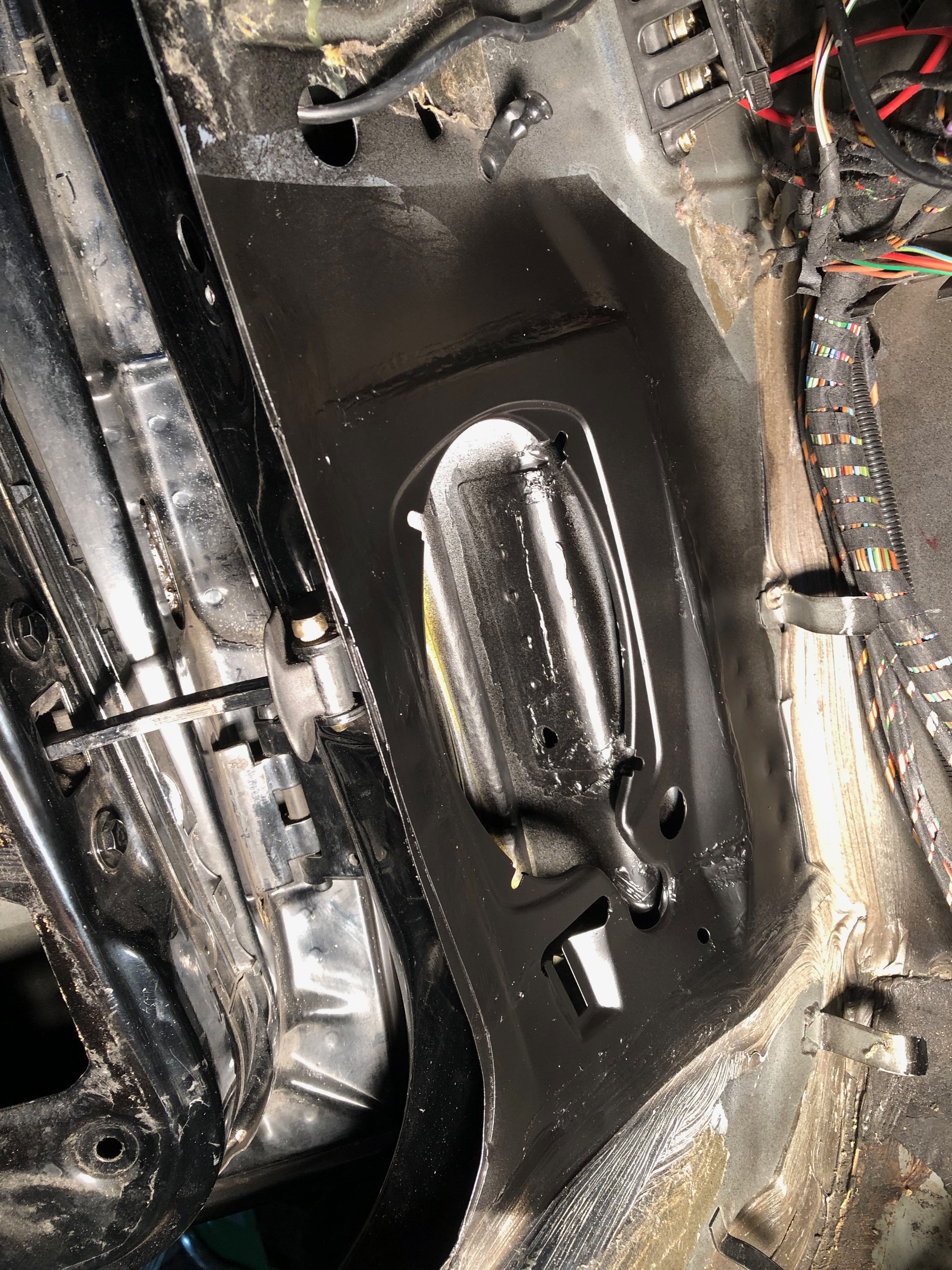
The black primer border looks ridiculous, but I didn't want to have the primer going all over the wiring that's still sitting under the dash.
But I had to post this one. That speaker hole enlargement project from some prior owner - including the frame hole - is what really got me thinking that I needed to roll up my sleeves and learn a bit more about how to fix some of these issues I was finding. And for me, the hidden details are what will make the car special - if it ever gets done. With all that said, I'm pretty happy with how the speaker panel fix came out. So getting the one done feels like a bit of a milestone.
Here's the final result:

The black primer border looks ridiculous, but I didn't want to have the primer going all over the wiring that's still sitting under the dash.
-
Adam W in MN
- Posts: 5052
- Joined: Feb 12, 2006 12:00 PM
- Location: Don't waste my motherf***in' time!
- Contact:
Re: Rebuilding My 1988 US-spec M5
Beautiful result and great attention to detail. You are really righting the wrongs inflicted on this car!
Re: Rebuilding My 1988 US-spec M5
So I took a first swag at cleaning up the battery box. When I first took out the trunk liner parts and removed the battery, it was obvious that there was rust & corrosion in the box, likely from a leaky battery. My main concern was that whatever had leaked out of the battery and into the box had also dripped down under the box and created issues in an area that I don't know how to get to.
My plan was to "curtain" off the battery box and media blast the box in place. Things went mostly according to plan, though it became difficult to do more than a few seconds of blasting at a time before the media would start to fill up the box.
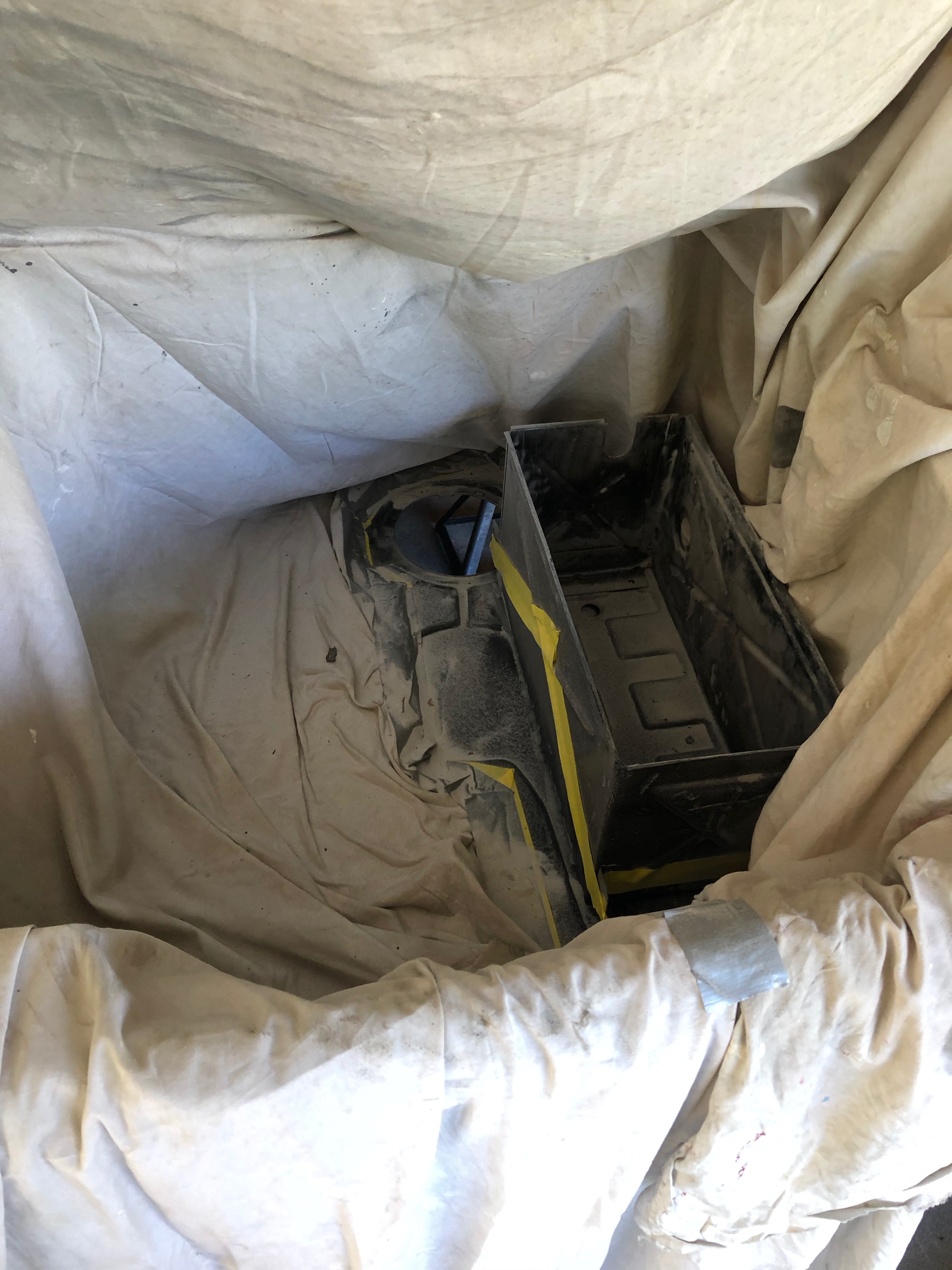
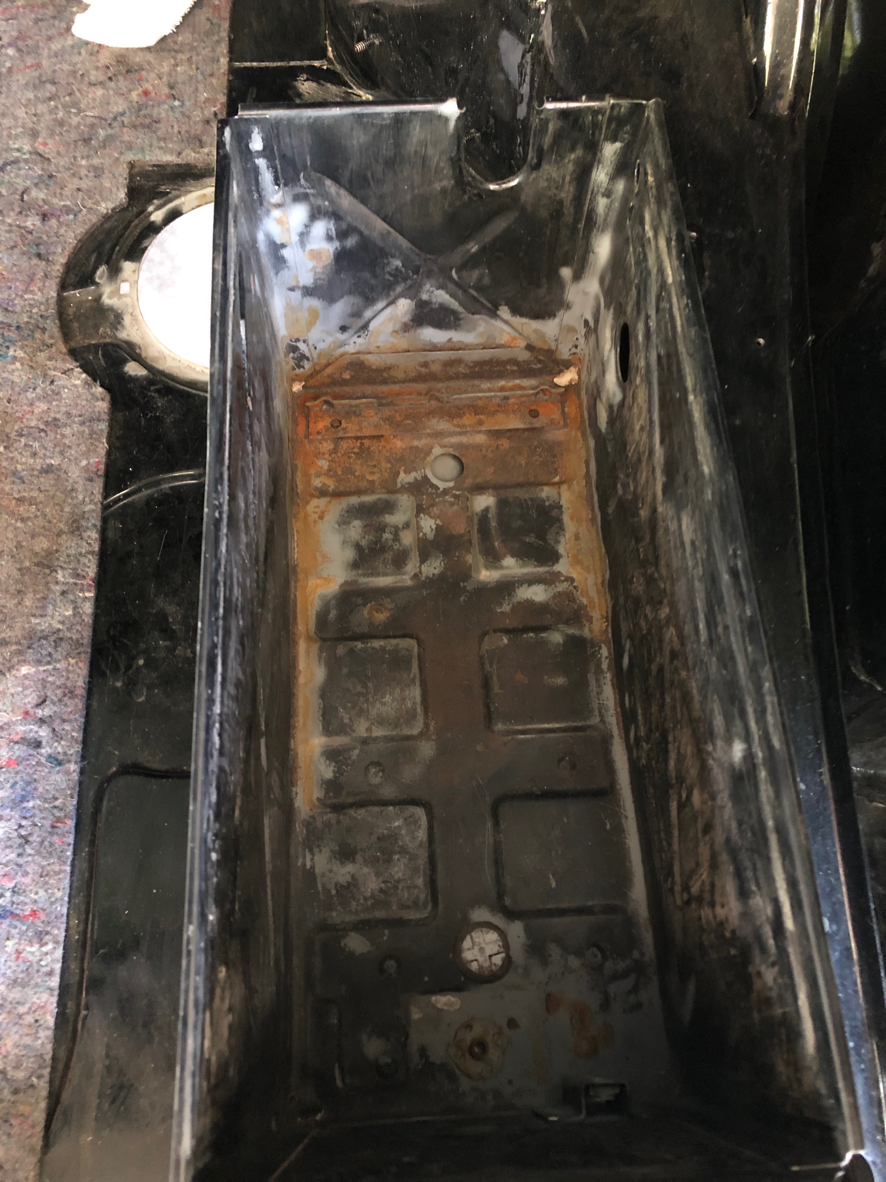
After some blasting, I think I'm OK with the existing box. I'll likely curtain just the box off again and give it another blast. That "after" pic isn't great, but if I get close up to that reddish residue looks more like film left over from the POR15 rust remover. The only damaged metal I'm seeing is that a portion of the forward battery hold-down is rusted away.
The better news is that I also managed to squeeze my bore scope into a few spots under the box (I'll edit this post with a pic if I can get the rig set up again), and I didn't see any rust at all under the box. It was dirty, but no corrosion that I could see. If anyone has any advice on how to get some primer or POR15 under there, please let me know, but my current thinking is that I'm not going to attempt to remove or replace the battery box.
EDIT: I got motivated and stuck the borescope in there again. After yesterday's cleaning, the scope actually slipped in more easily.
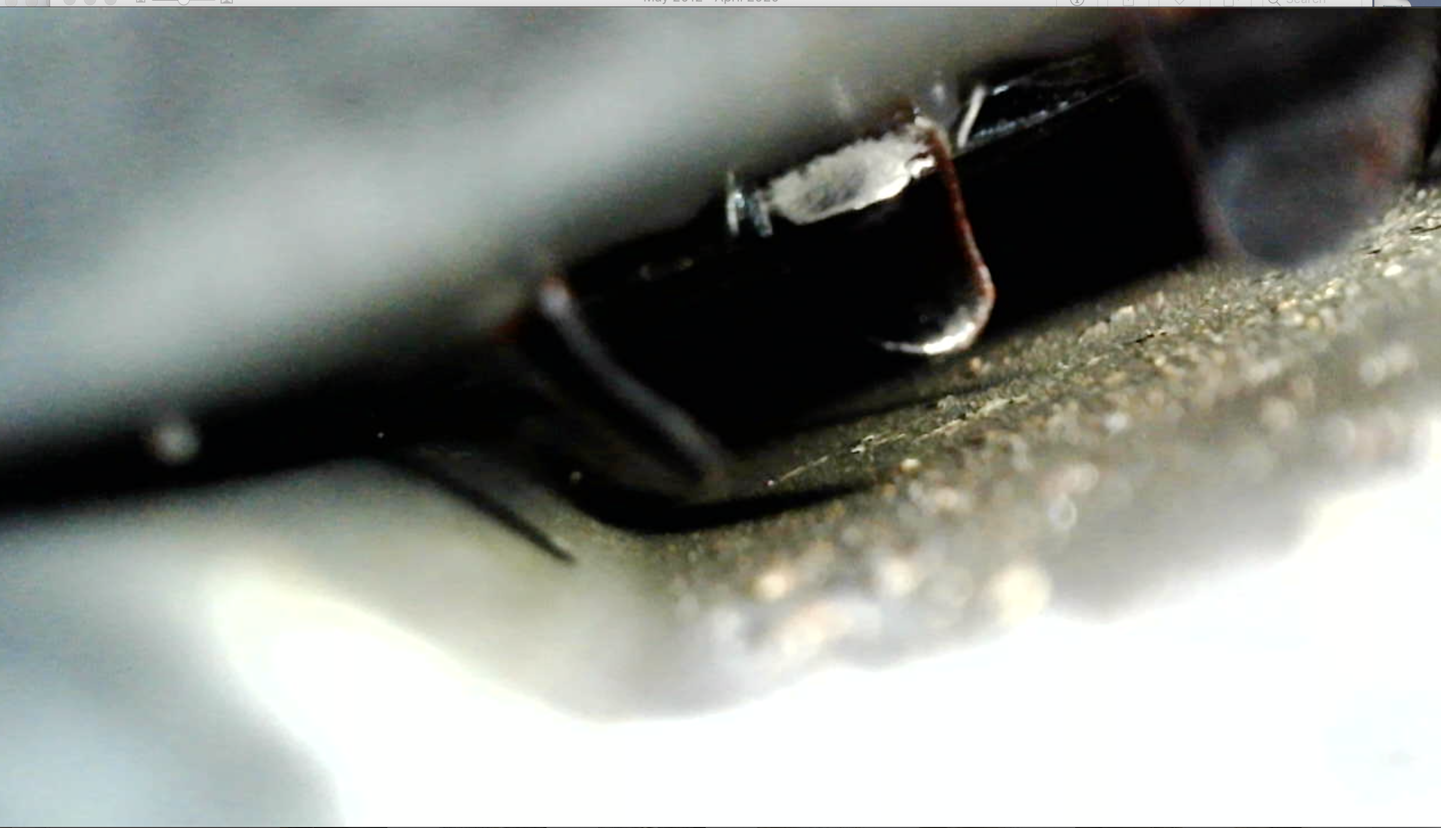
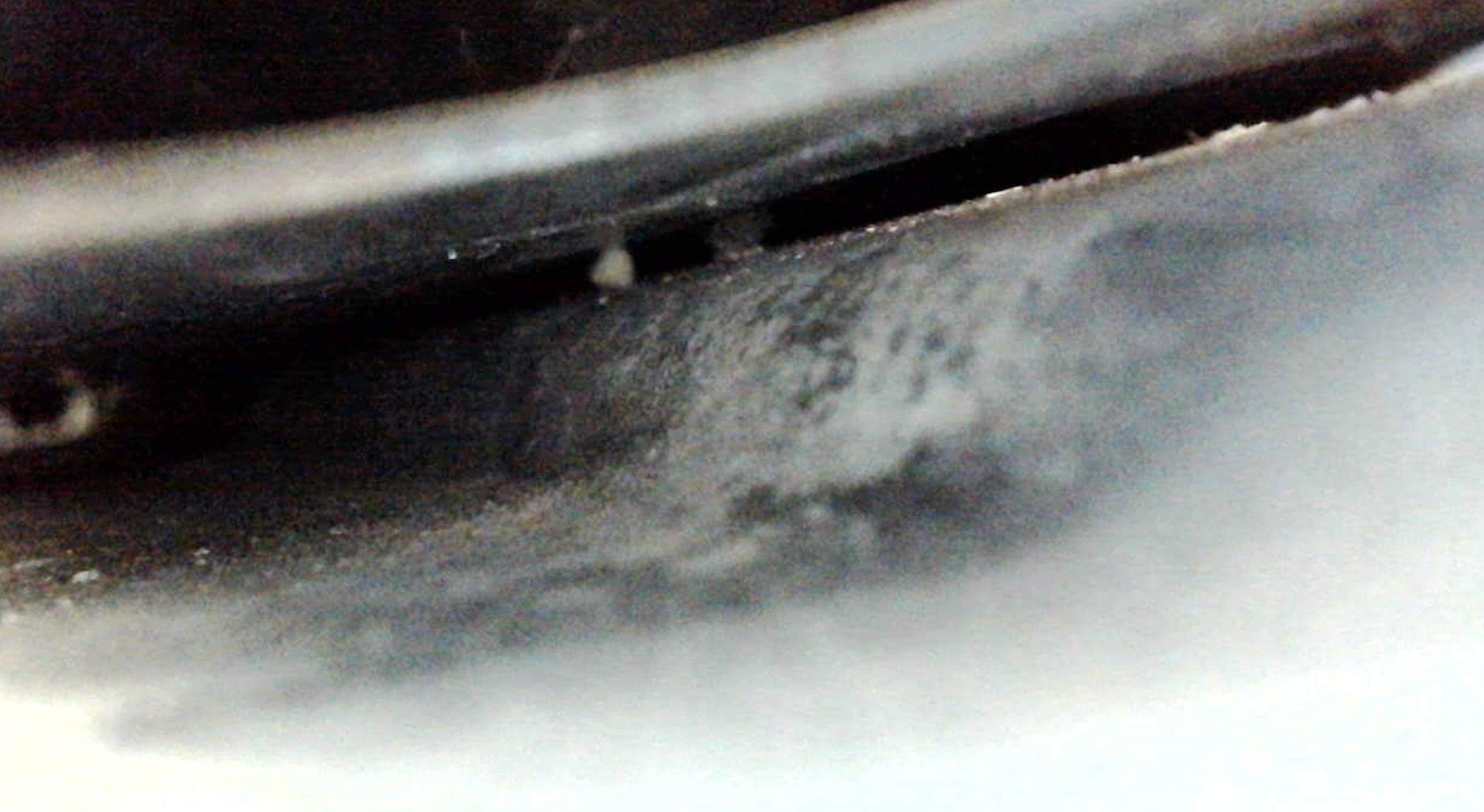
Those were the two dirtiest spots I could find. I'm pleasantly surprised a the lack of corrosion in there, and I think I'll leave the box in place. Just clean it up a bit more, POR15, paint.
My plan was to "curtain" off the battery box and media blast the box in place. Things went mostly according to plan, though it became difficult to do more than a few seconds of blasting at a time before the media would start to fill up the box.


After some blasting, I think I'm OK with the existing box. I'll likely curtain just the box off again and give it another blast. That "after" pic isn't great, but if I get close up to that reddish residue looks more like film left over from the POR15 rust remover. The only damaged metal I'm seeing is that a portion of the forward battery hold-down is rusted away.
The better news is that I also managed to squeeze my bore scope into a few spots under the box (I'll edit this post with a pic if I can get the rig set up again), and I didn't see any rust at all under the box. It was dirty, but no corrosion that I could see. If anyone has any advice on how to get some primer or POR15 under there, please let me know, but my current thinking is that I'm not going to attempt to remove or replace the battery box.
EDIT: I got motivated and stuck the borescope in there again. After yesterday's cleaning, the scope actually slipped in more easily.


Those were the two dirtiest spots I could find. I'm pleasantly surprised a the lack of corrosion in there, and I think I'll leave the box in place. Just clean it up a bit more, POR15, paint.
Re: Rebuilding My 1988 US-spec M5
I didn't know about this thread. Regret. Fixed.
Re: Rebuilding My 1988 US-spec M5
Given the condition under the box (good) I think your best bet is to get some good/decent rust-preventative primer (Rustoleum, Krylon) or even some Ruststop (Eastwood), see if you can use one of the plastic "straws/nozzles" (sorry, don't know the proper name) you get on brake cleaner etc. and get it in there under the box. 
As to the interior of the box I would likely use a Dremmel tool with wire brush wheels to get into the tight corners (you will likely go through a lot of them, they're pretty fragile little things). Or you can put on the stone wheel bit also.
As to the interior of the box I would likely use a Dremmel tool with wire brush wheels to get into the tight corners (you will likely go through a lot of them, they're pretty fragile little things). Or you can put on the stone wheel bit also.
Re: Rebuilding My 1988 US-spec M5
Vince: Yup, getting the inside of the battery box was a total pain. I used a wire wheel on my drill to start, but as you note, that won't get into the corners. I'd considered using a Dremel, but I don't think HF carries enough of those wire wheel bit kits in their entire inventory to get that job done. So ... I ended up media-blasting the box a couple of times and scrubbed in that gap under the box by threading small rags through that gap. I knew the media blasting was going to be super-unpleasant, so I hung sheeting & taped off as much stuff as I could. I still ended up wearing glass grit everywhere. But the box got clean! Then I did a couple of coats of POR15 and then primer. Haven't painted it yet, but my hope is to refresh the entire trunk and I'll complete the battery box at that time.
Speaking of refreshing the trunk, if anyone knows of a good source for getting replacement felt padding (similar industrial look, similar thickness, wide enough to be able to cut the entire part without a seam), please let me know.
Also, great call on the Eastwood stuff. I think you may be taking about EASTWOOD INTERNAL FRAME COATING? It comes with a hose so that you can snake it into nooks & crannies. I was planning on using it in the "C" channel behind the rear valance and in the rockers, but using it under the battery box is a great call as well.
In any case, I'm continuing to make progress. The irony of the COVID situation is that with the stay-in-place orders I have plenty of extra time to work on the car, but getting parts has become more difficult. FCP & ECS orders that used to take a few days are now getting stretched to a couple of weeks. I assume that various shutdowns in the supply chain are affecting all of this.
The practical result for me has been that I have had a bunch of sub-projects (front & rear strut assemblies, diff refresh, some painting projects, front euro bumper mounts) that have been just a part or two from completion. Most of that has resolved, so I should be able to start putting the suspension and undercarriage back on in the very near future. And that's key because ... I think I found a shop that can do a good job painting the whole car. But getting the car there means it has to be a rolling shell (including steering and the parking brake). I would really like to get the car to them as soon as possible in the hopes that they can spend a bit more time & attention on my car while their business is slow.
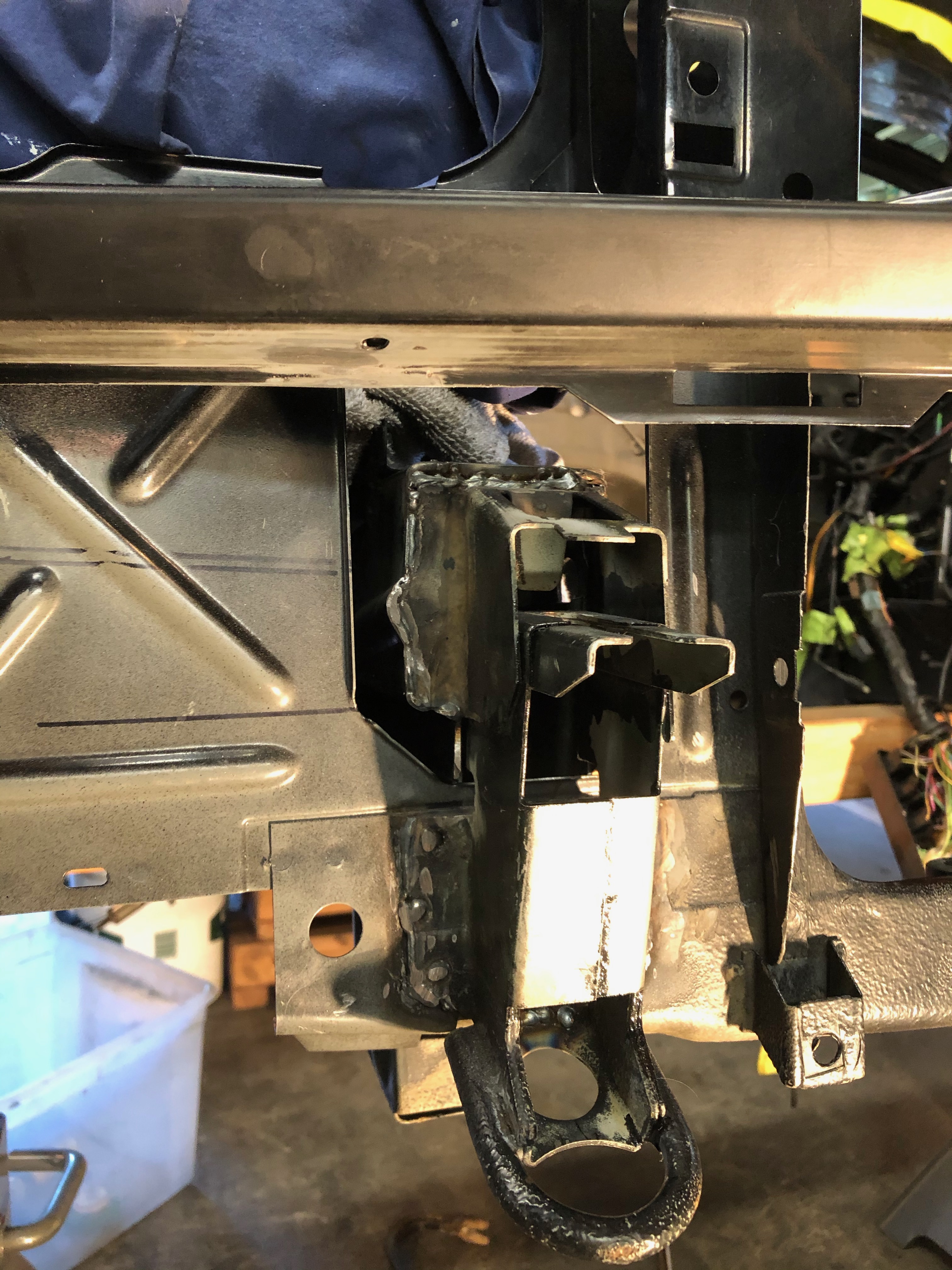
Here's the install of the front euro bumper mounts. First, these are the donor mounts that took forever to get here (literally three round trips between here & AZ; thanks USPS).
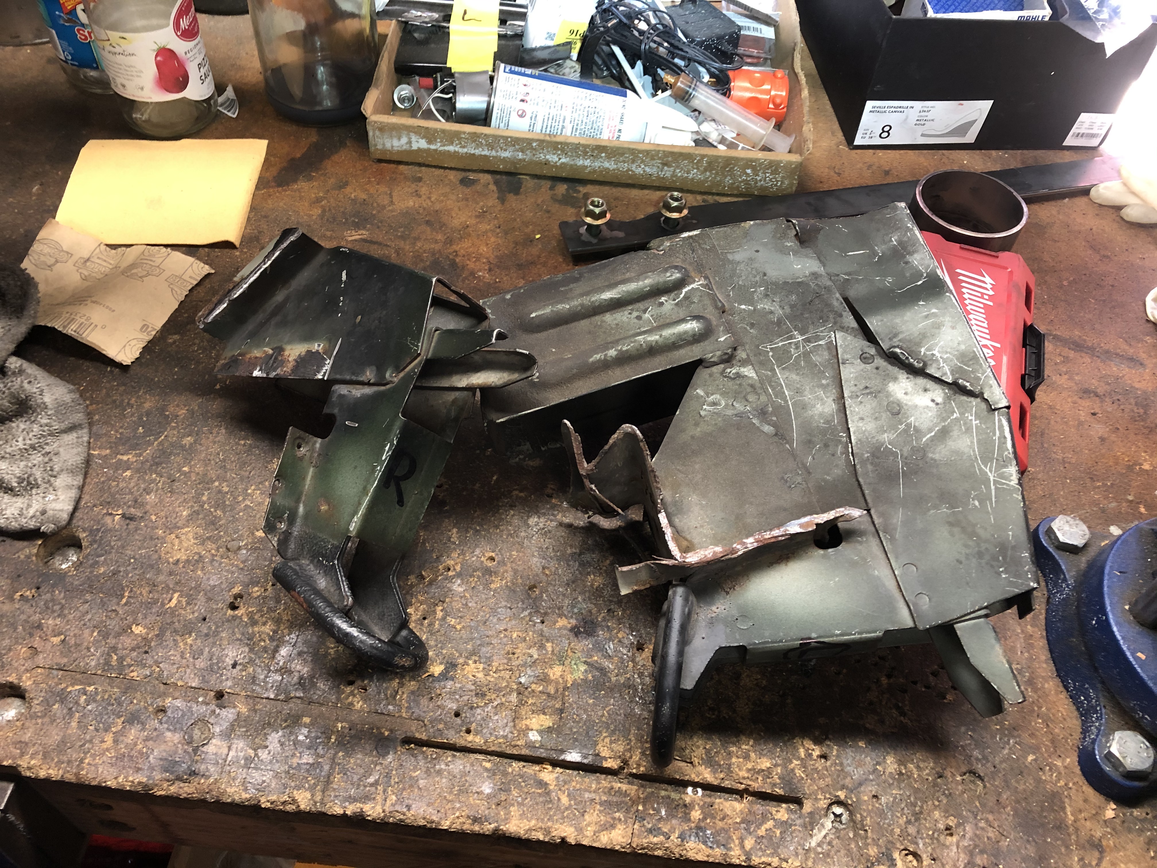
US bumper shock tubes cut off and front tow hook assemblies removed:
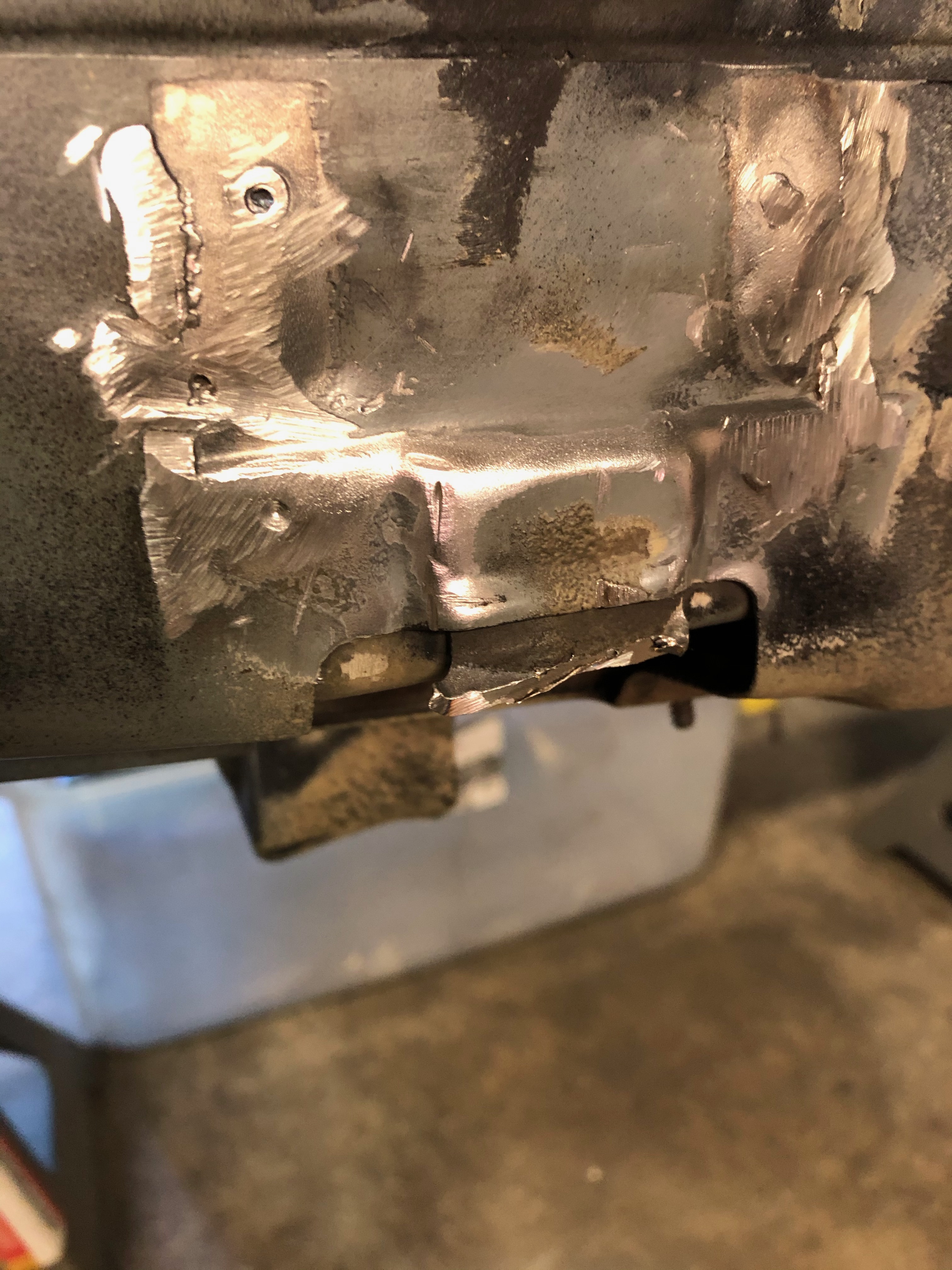
Euros welded in:
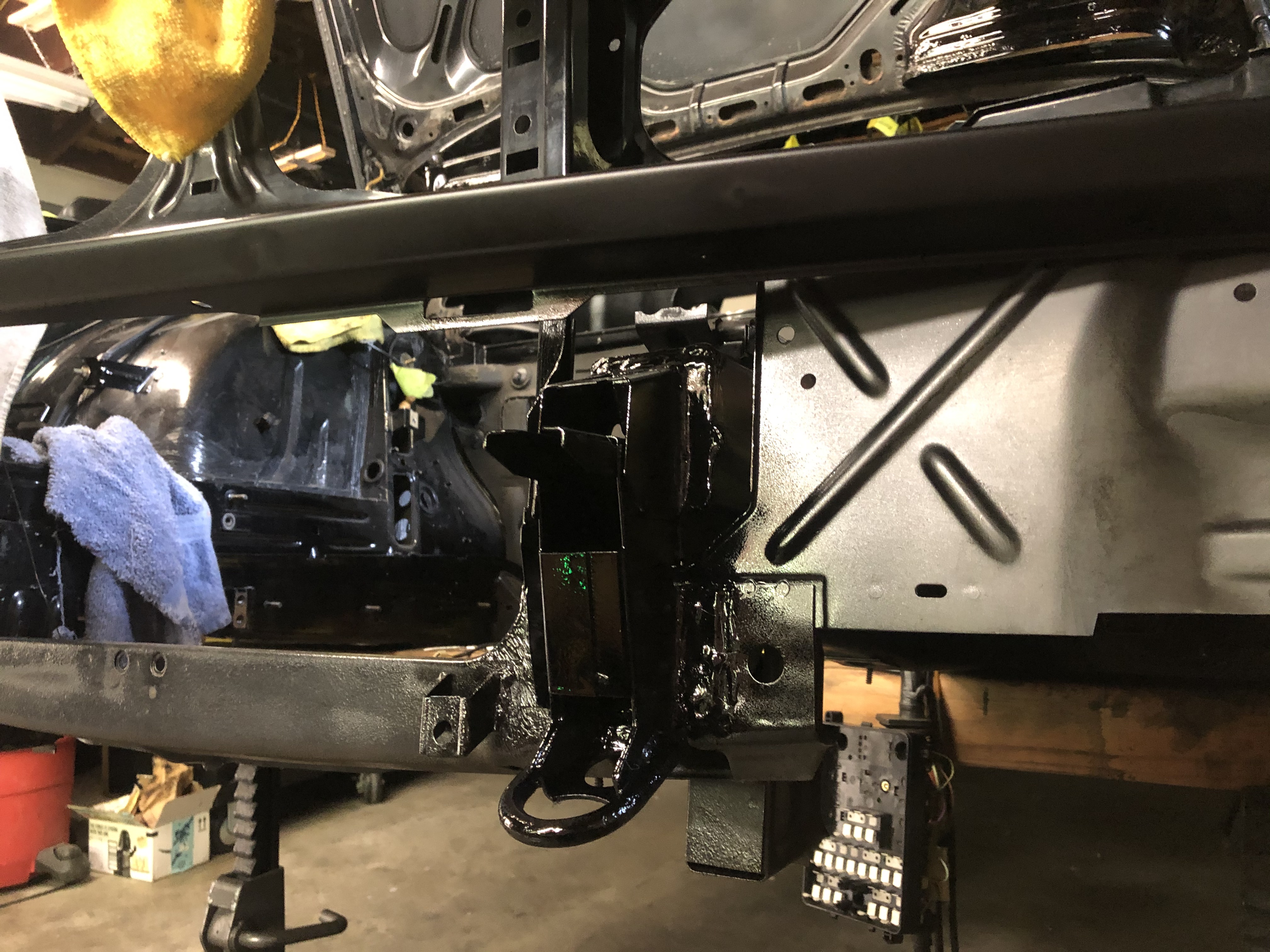
And after seam sealer, primer & paint (actual 2k BMW 086 Schwartz!):
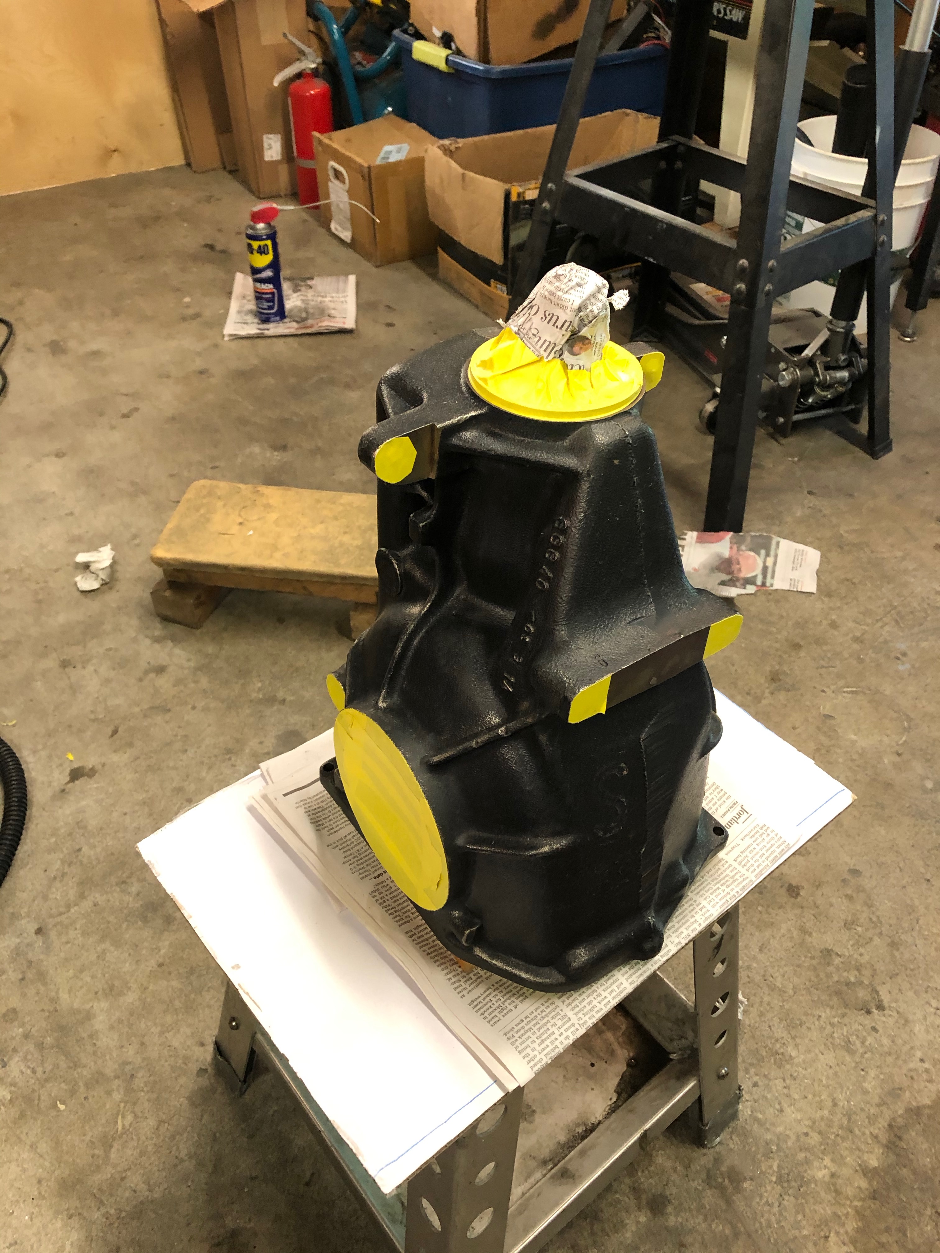
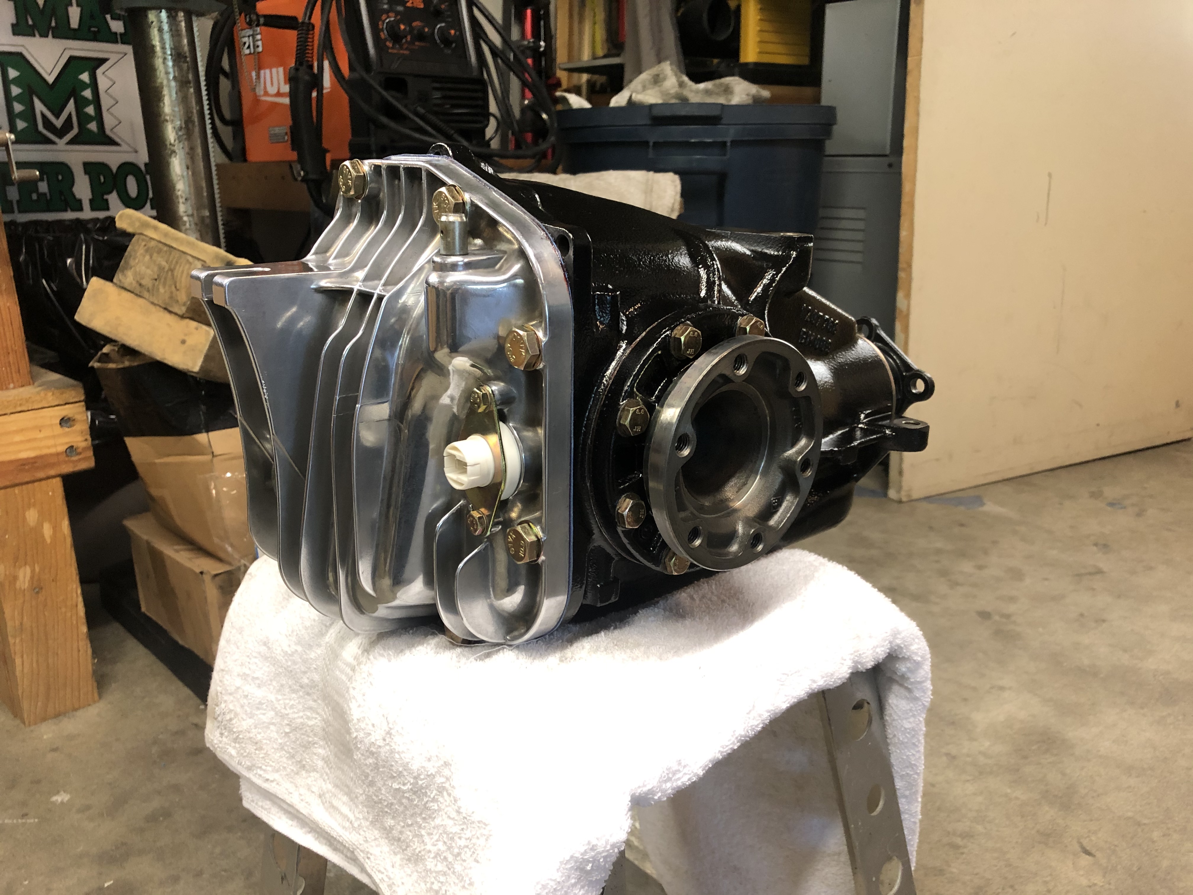
Diff refresh. Goal here was not to rebuild the entire thing, but instead to reseal it and make it nice & purty. And internal inspection showed that the bearings & races were pristine, so there was no reason to go beyond just a reseal anyhow. Oh, BTW, if I haven't said it before, I suck at remembering to get the "before" pics, so I've got nothing showing how grimy this was to start with.
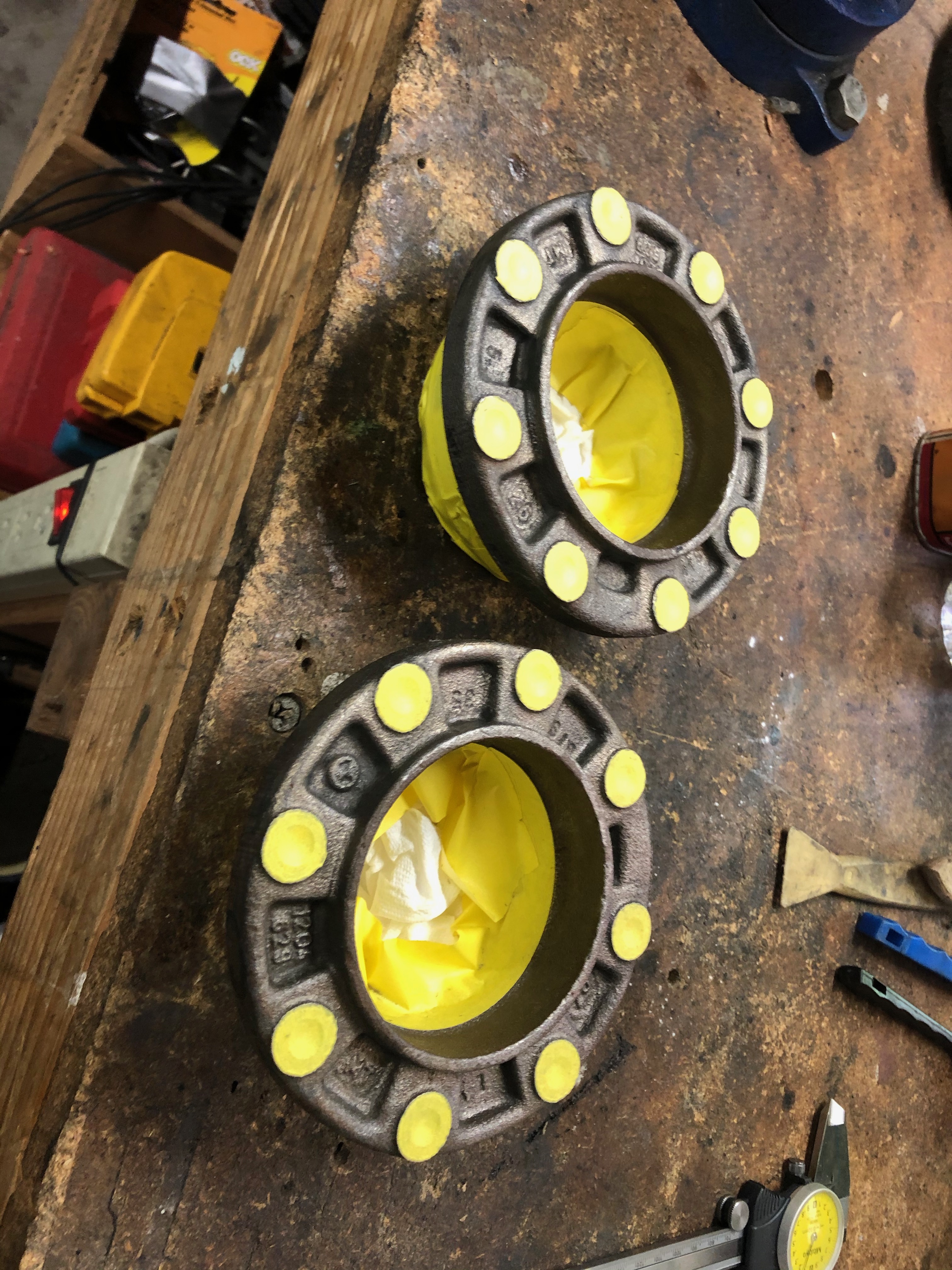
Painting the case & output shaft caps:
Fully reassembled:
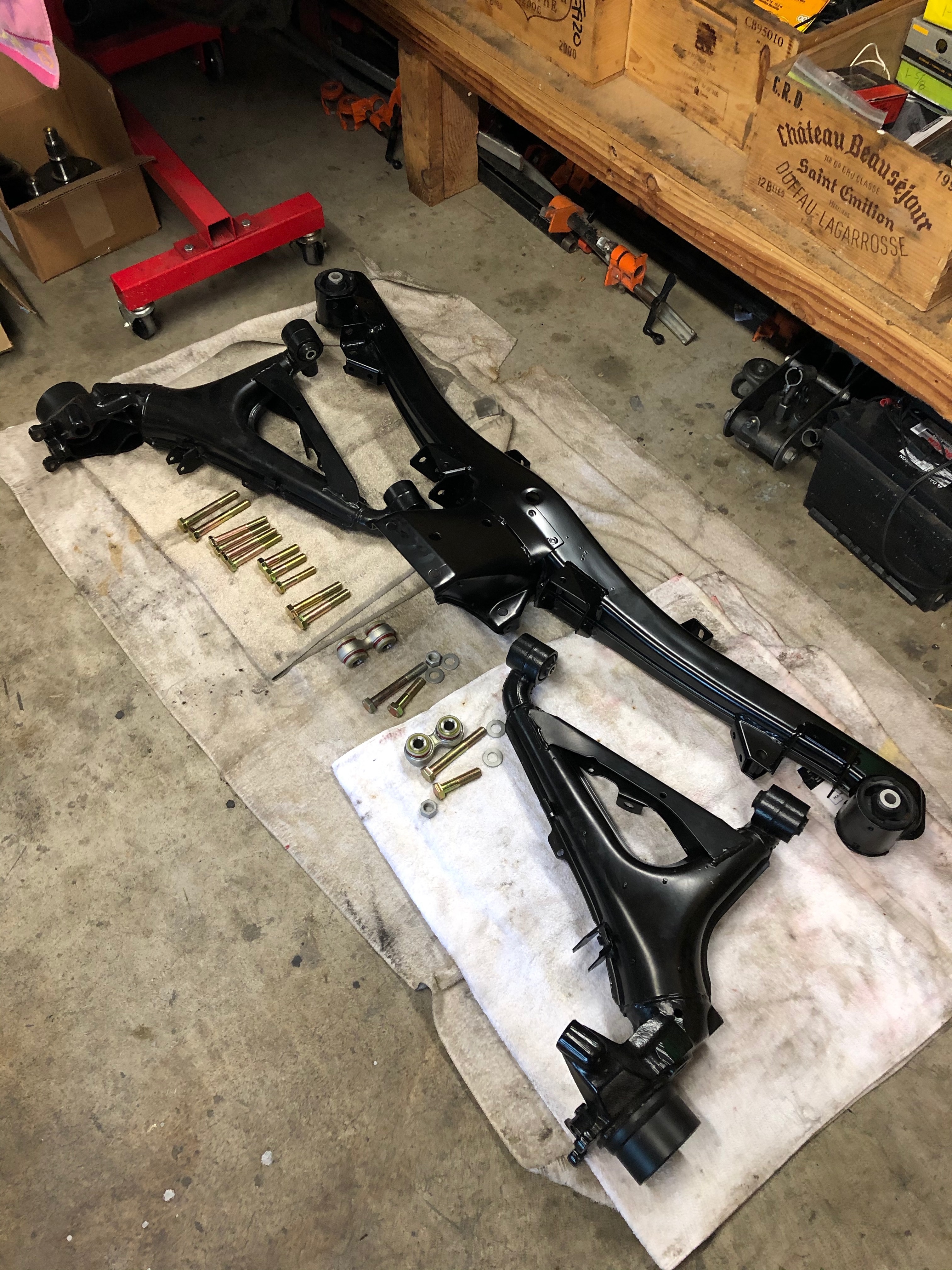
Starting to put the undercarriage subassemblies back together.
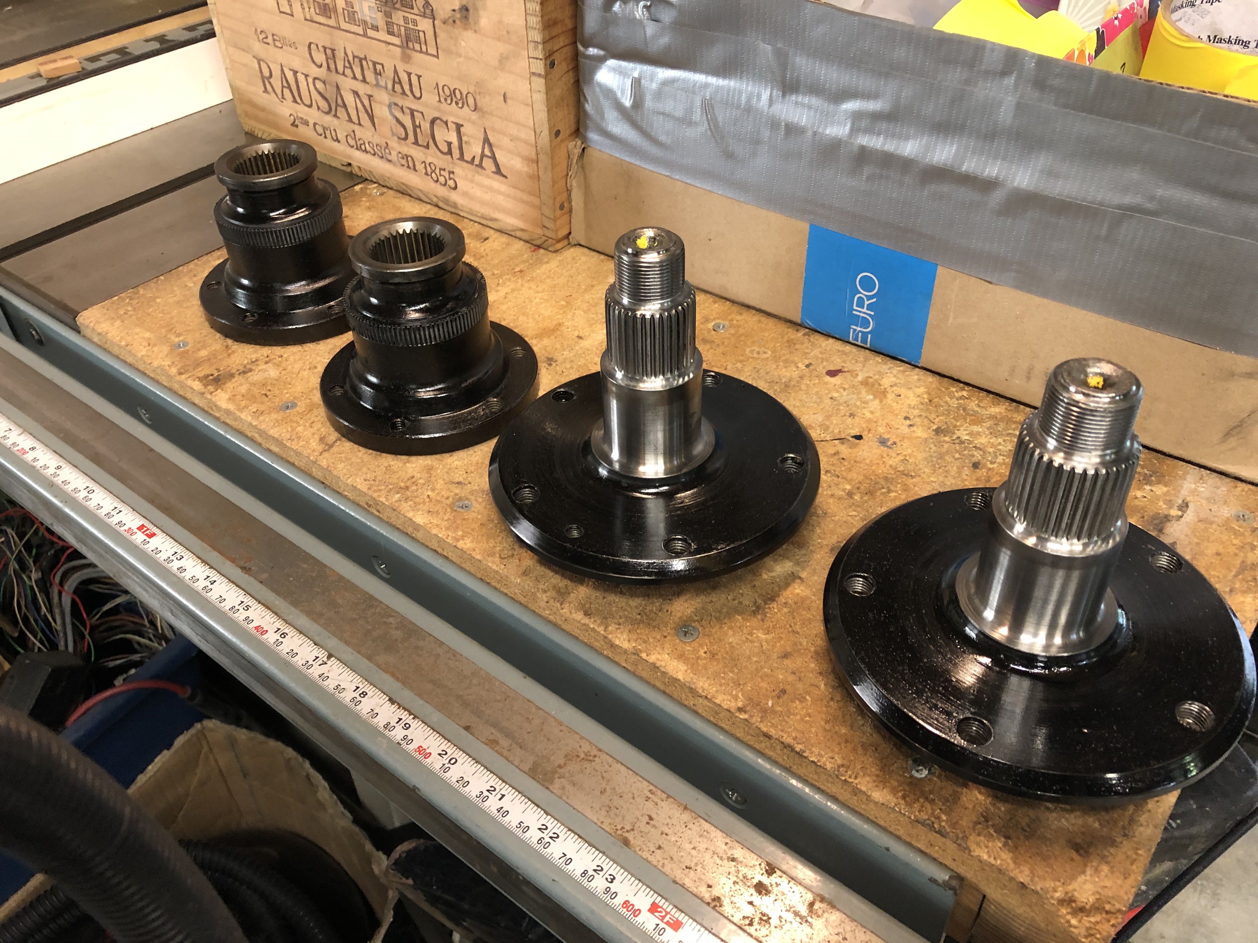
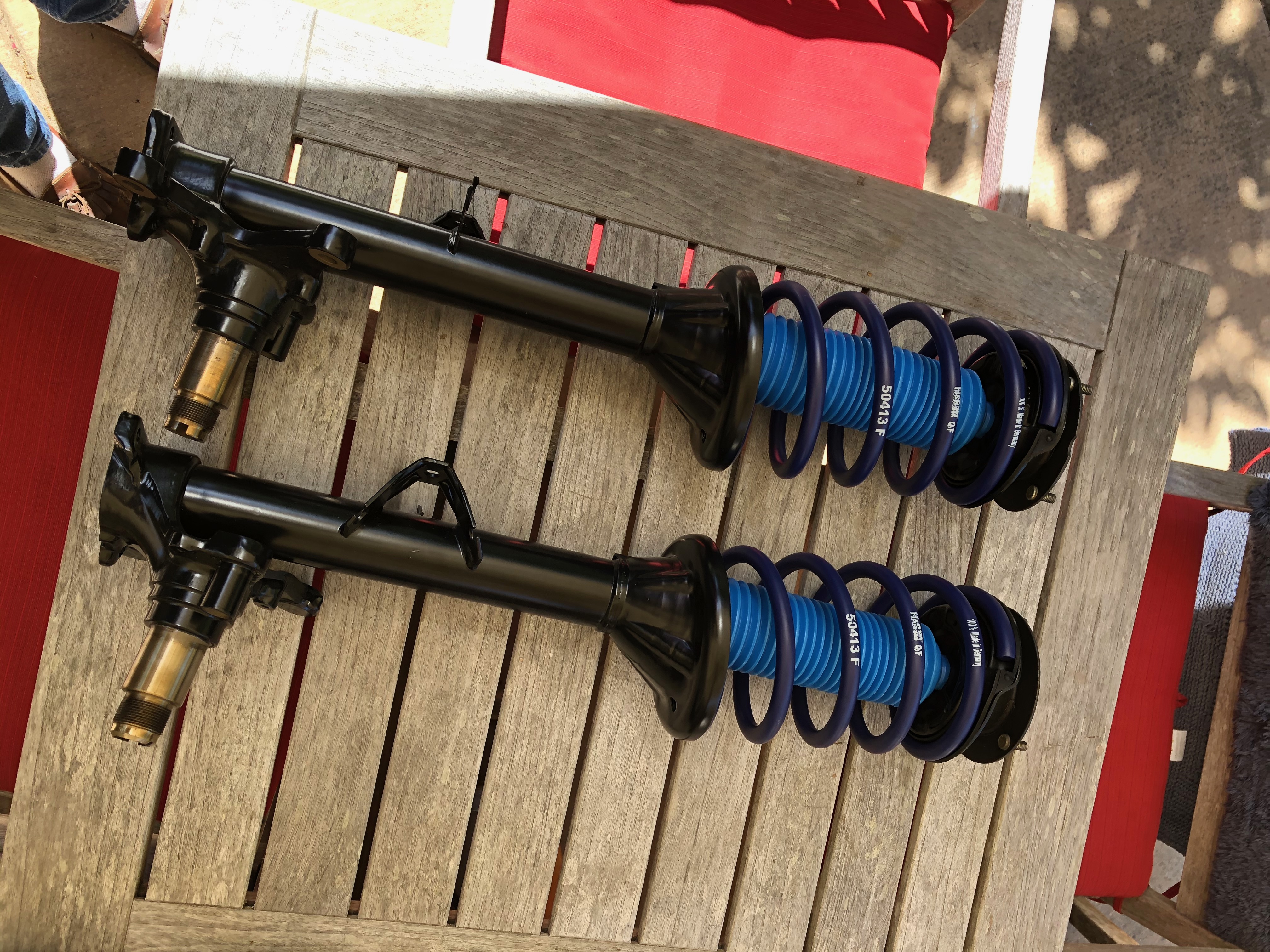
Since those pics were taken, I've also pressed the rear spindles back into the RTAs. At first, I put the RTAs back onto the rear subframe and then tried to press the outer spindles in. That was a total fail. Some research here on the forum indicated that pressing / pulling those outer spindles was a real pain, and it took me a while to remember how I'd done this last time. Of course, if you have the RTAs off the car, no special tricks are needed to get the spindle back in ... they can just be pressed into the bearings on the press. So, I took the RTAs off again, set up the handy-dandy HF 12-ton and they slipped right in. Forgot to get a pic, of course. I used a 46mm impact socket on the inside to support the inner race as I pressed the spindle in from the top.
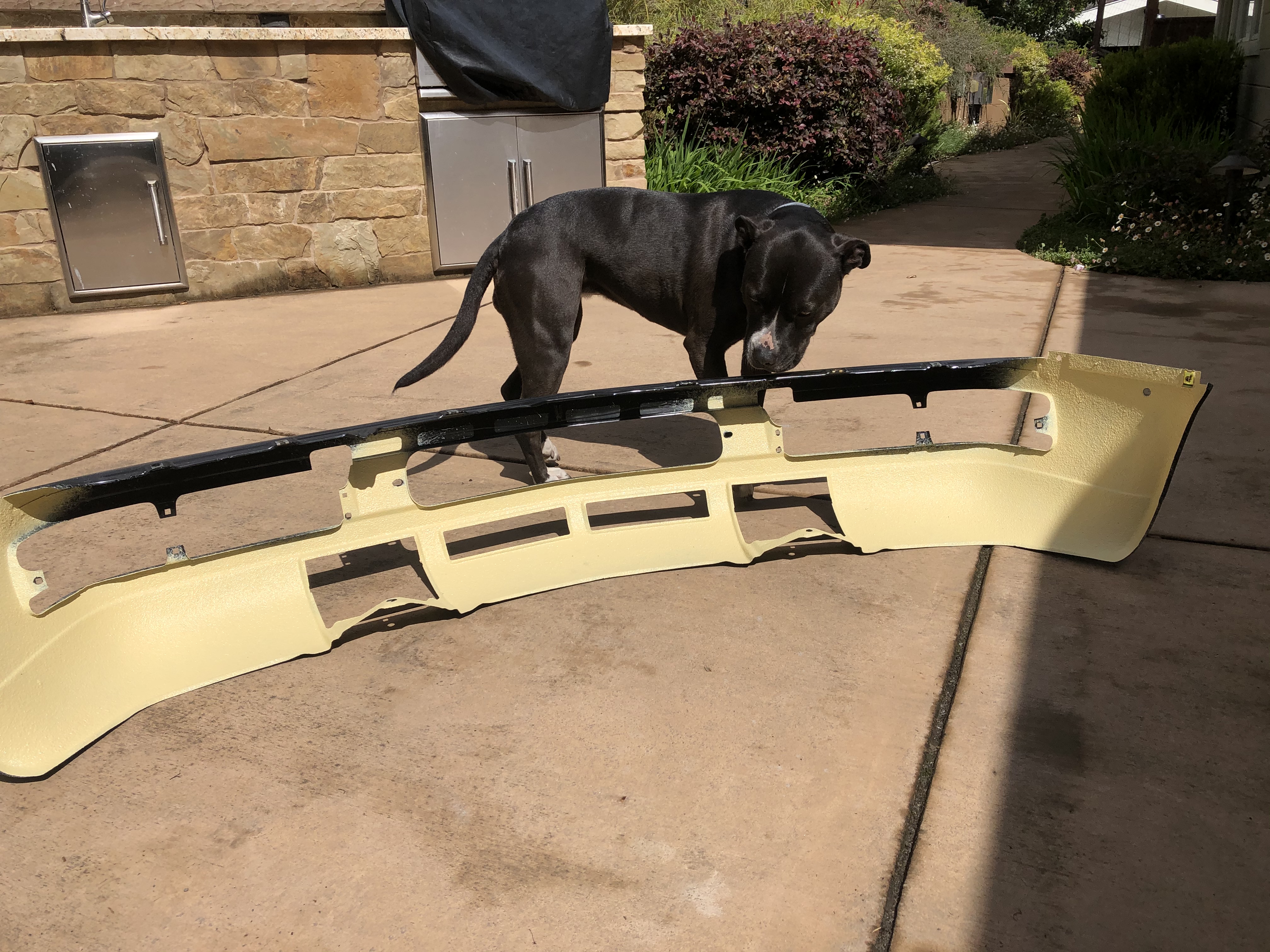
I also got my SEM seam sealer sprayer set up to shoot the front & rear valences (both are new euro parts) and the repaired frame rails. Here's the front valance undergoing final inspection:
And the frame rails (sorry for the shitty pic):
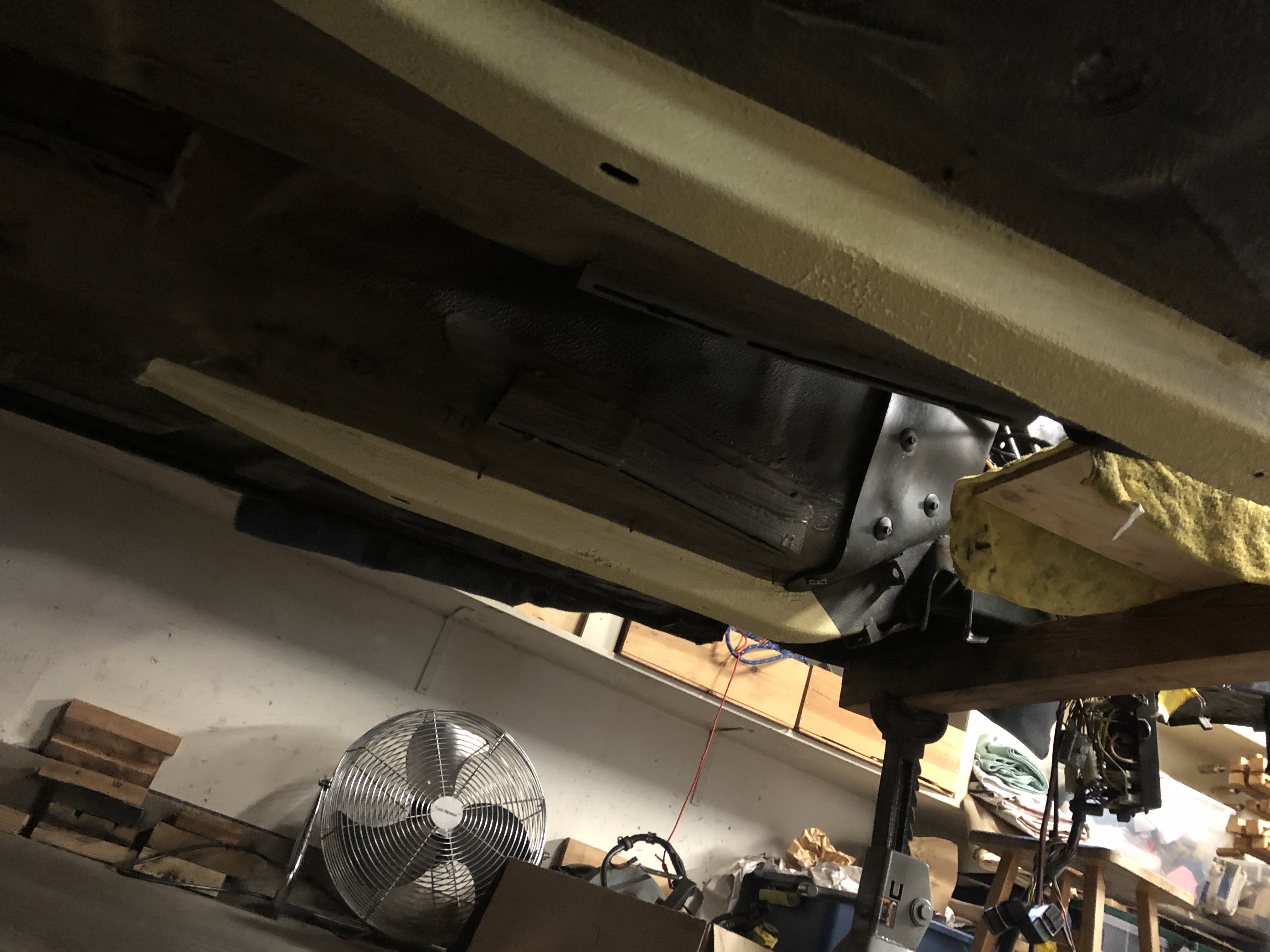
One thing that's painfully - painfully - apparent to me here is that the SEM seam sealer isn't beige - not even close. It's so yellow it makes me want to go apply to the University of Michigan so I can hear all about how it's really "maize." I'm not sure what I'm going to do here. Options could include spraying some black / olive drab paint on there to "dirty" it up a bit and mimic the original factory overspray, or buy more SEM in both "beige" and black and mix them together to see if I can get closer to the look of the 30-year-old factory beige coating. The contrast to the old sealer is so stark that I really don't want to leave it like that.
Last update ... I know it can be a bit controversial around these parts, but given all the effort I'm putting into getting the undercarriage looking new, I didn't want to have dirty, hazy, worn-looking wheel wells as the backdrop for all that. I tried my best to clean them up as-is, but calcified BMW protective spray (not sure what it was ... creosote? Whatever that whitish-yellow crust is that's in a variety of palaces underbody and in the engine compartment) had gotten crusted up with embedded sand & grit, and the condition of the paint in there was pretty bad even at its best. So, I decided to respray the wells. After getting some detailed paint prep advice and spending several hours per well getting all the caked-on crap out of there, I resprayed with matching 2k BMW 086 Schwartz paint. I'm pretty pleased with the result even if my iPhone isn't capturing it very well.
After prep:
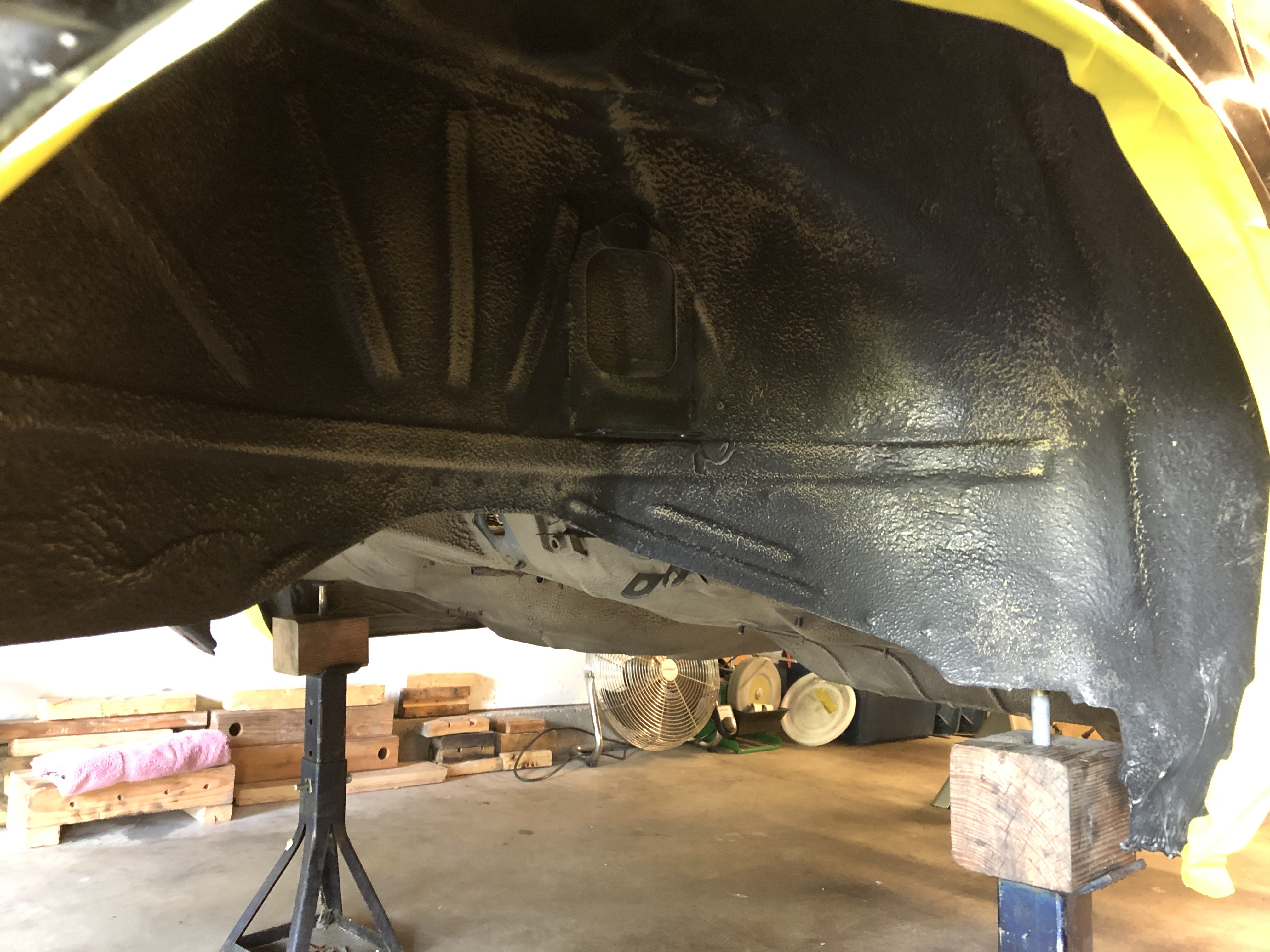
After painting:
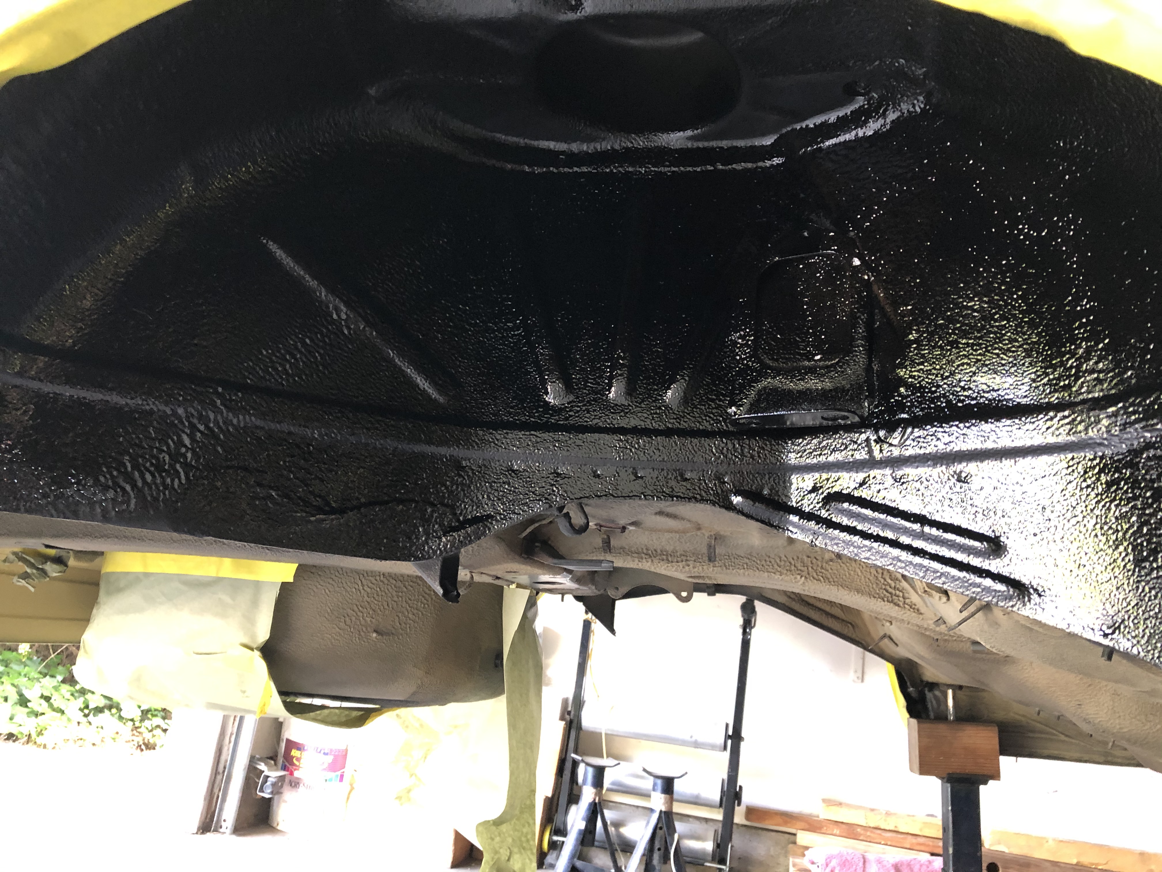
That's all for now. I'm hoping to have the shell back down on the ground on its own wheels & tires and then off to pain in the next couple of weeks - assuming I can find all the needed parts in storage. Ugh - fingers crossed ...
Speaking of refreshing the trunk, if anyone knows of a good source for getting replacement felt padding (similar industrial look, similar thickness, wide enough to be able to cut the entire part without a seam), please let me know.
Also, great call on the Eastwood stuff. I think you may be taking about EASTWOOD INTERNAL FRAME COATING? It comes with a hose so that you can snake it into nooks & crannies. I was planning on using it in the "C" channel behind the rear valance and in the rockers, but using it under the battery box is a great call as well.
In any case, I'm continuing to make progress. The irony of the COVID situation is that with the stay-in-place orders I have plenty of extra time to work on the car, but getting parts has become more difficult. FCP & ECS orders that used to take a few days are now getting stretched to a couple of weeks. I assume that various shutdowns in the supply chain are affecting all of this.
The practical result for me has been that I have had a bunch of sub-projects (front & rear strut assemblies, diff refresh, some painting projects, front euro bumper mounts) that have been just a part or two from completion. Most of that has resolved, so I should be able to start putting the suspension and undercarriage back on in the very near future. And that's key because ... I think I found a shop that can do a good job painting the whole car. But getting the car there means it has to be a rolling shell (including steering and the parking brake). I would really like to get the car to them as soon as possible in the hopes that they can spend a bit more time & attention on my car while their business is slow.
Here's the install of the front euro bumper mounts. First, these are the donor mounts that took forever to get here (literally three round trips between here & AZ; thanks USPS).

US bumper shock tubes cut off and front tow hook assemblies removed:

Euros welded in:

And after seam sealer, primer & paint (actual 2k BMW 086 Schwartz!):

Diff refresh. Goal here was not to rebuild the entire thing, but instead to reseal it and make it nice & purty. And internal inspection showed that the bearings & races were pristine, so there was no reason to go beyond just a reseal anyhow. Oh, BTW, if I haven't said it before, I suck at remembering to get the "before" pics, so I've got nothing showing how grimy this was to start with.
Painting the case & output shaft caps:


Fully reassembled:

Starting to put the undercarriage subassemblies back together.


Since those pics were taken, I've also pressed the rear spindles back into the RTAs. At first, I put the RTAs back onto the rear subframe and then tried to press the outer spindles in. That was a total fail. Some research here on the forum indicated that pressing / pulling those outer spindles was a real pain, and it took me a while to remember how I'd done this last time. Of course, if you have the RTAs off the car, no special tricks are needed to get the spindle back in ... they can just be pressed into the bearings on the press. So, I took the RTAs off again, set up the handy-dandy HF 12-ton and they slipped right in. Forgot to get a pic, of course. I used a 46mm impact socket on the inside to support the inner race as I pressed the spindle in from the top.
I also got my SEM seam sealer sprayer set up to shoot the front & rear valences (both are new euro parts) and the repaired frame rails. Here's the front valance undergoing final inspection:

And the frame rails (sorry for the shitty pic):

One thing that's painfully - painfully - apparent to me here is that the SEM seam sealer isn't beige - not even close. It's so yellow it makes me want to go apply to the University of Michigan so I can hear all about how it's really "maize." I'm not sure what I'm going to do here. Options could include spraying some black / olive drab paint on there to "dirty" it up a bit and mimic the original factory overspray, or buy more SEM in both "beige" and black and mix them together to see if I can get closer to the look of the 30-year-old factory beige coating. The contrast to the old sealer is so stark that I really don't want to leave it like that.
Last update ... I know it can be a bit controversial around these parts, but given all the effort I'm putting into getting the undercarriage looking new, I didn't want to have dirty, hazy, worn-looking wheel wells as the backdrop for all that. I tried my best to clean them up as-is, but calcified BMW protective spray (not sure what it was ... creosote? Whatever that whitish-yellow crust is that's in a variety of palaces underbody and in the engine compartment) had gotten crusted up with embedded sand & grit, and the condition of the paint in there was pretty bad even at its best. So, I decided to respray the wells. After getting some detailed paint prep advice and spending several hours per well getting all the caked-on crap out of there, I resprayed with matching 2k BMW 086 Schwartz paint. I'm pretty pleased with the result even if my iPhone isn't capturing it very well.
After prep:

After painting:

That's all for now. I'm hoping to have the shell back down on the ground on its own wheels & tires and then off to pain in the next couple of weeks - assuming I can find all the needed parts in storage. Ugh - fingers crossed ...
Re: Rebuilding My 1988 US-spec M5
Wow, great progress! and nice documented!
I will keep folowing this thread!
I will keep folowing this thread!
Re: Rebuilding My 1988 US-spec M5
Time for an update. The stay-in-place orders + working from home + general slowdown in business has given me puh-lenty of time to work on this beast. The thought also occurred to me that with the business slow-down, I might have an easier time of finding a bodyshop to do a full-body repaint. With that in mind, I've been focusing on getting the car back down on its own wheels so that it's legitimately a "rolling shell" that a body shop could work on.
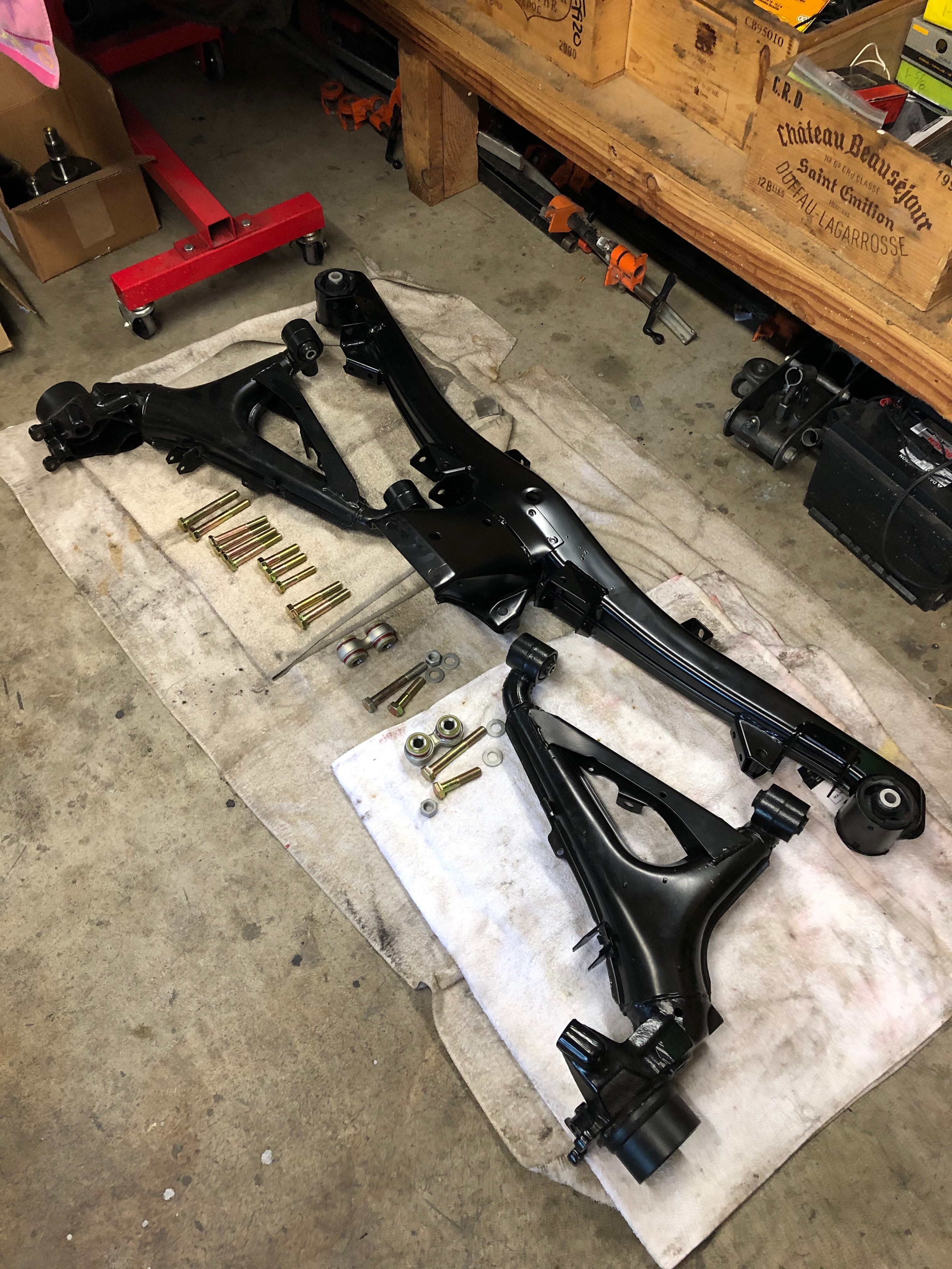
So, after finishing the front euro bumper & valance work, I turned to assembling & reinstalling everything underneath. Rear subframe laid out in prep for reassembly:
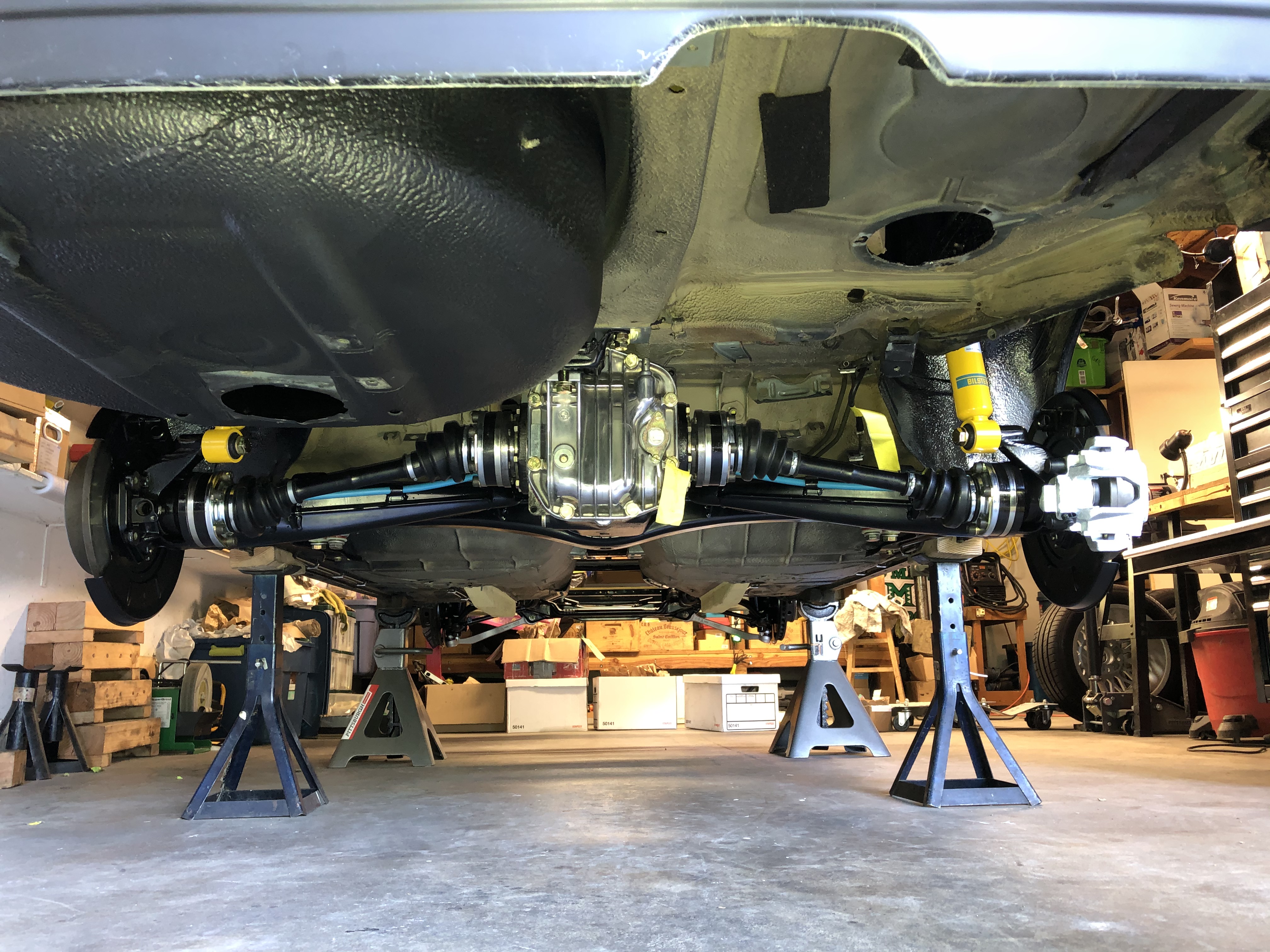
And installed:
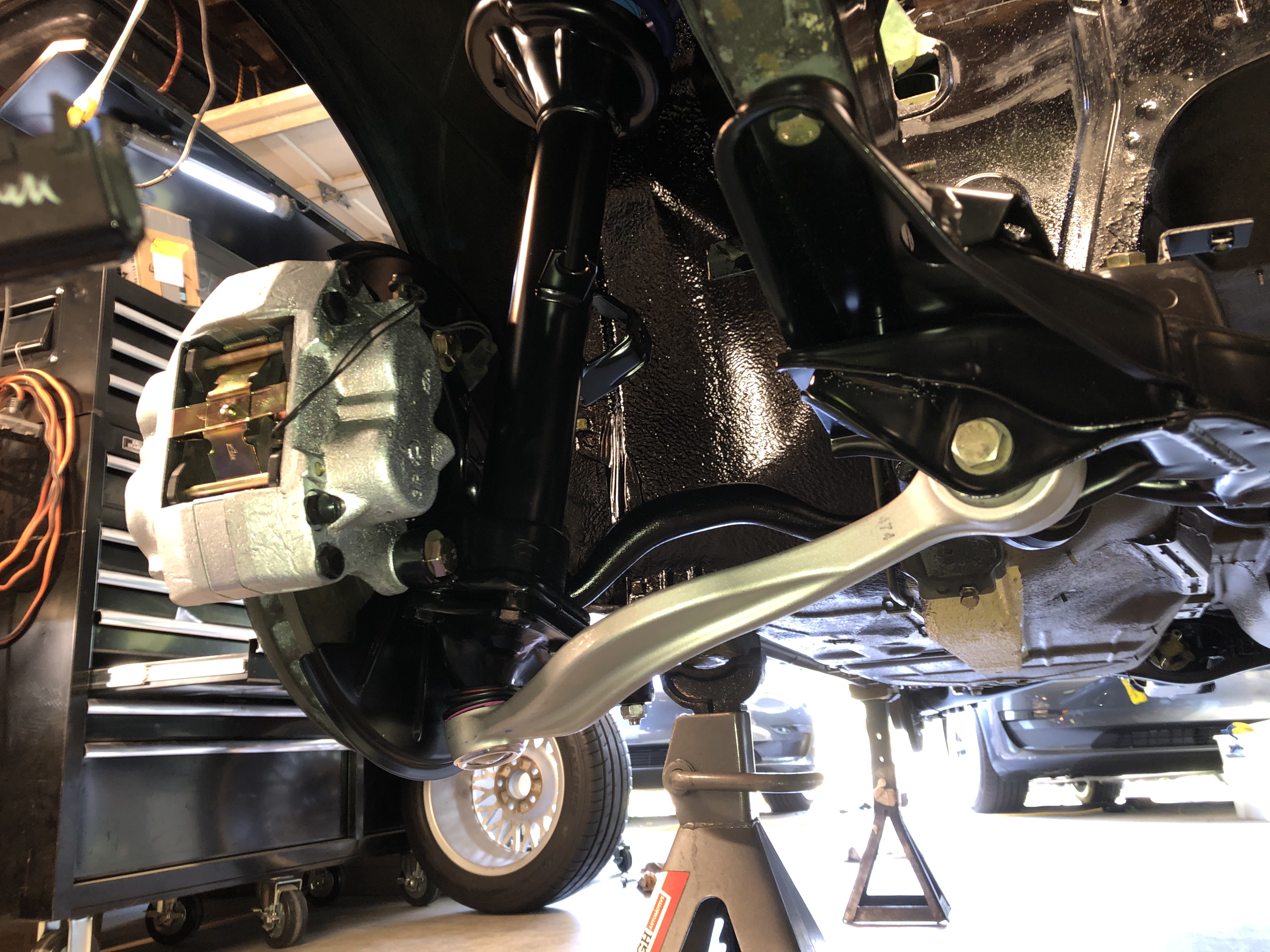
Fronts as well (brake caliper is there just for dry fitting):
And back down (almost) on the ground sort-of-kind-of actually looking like a car:
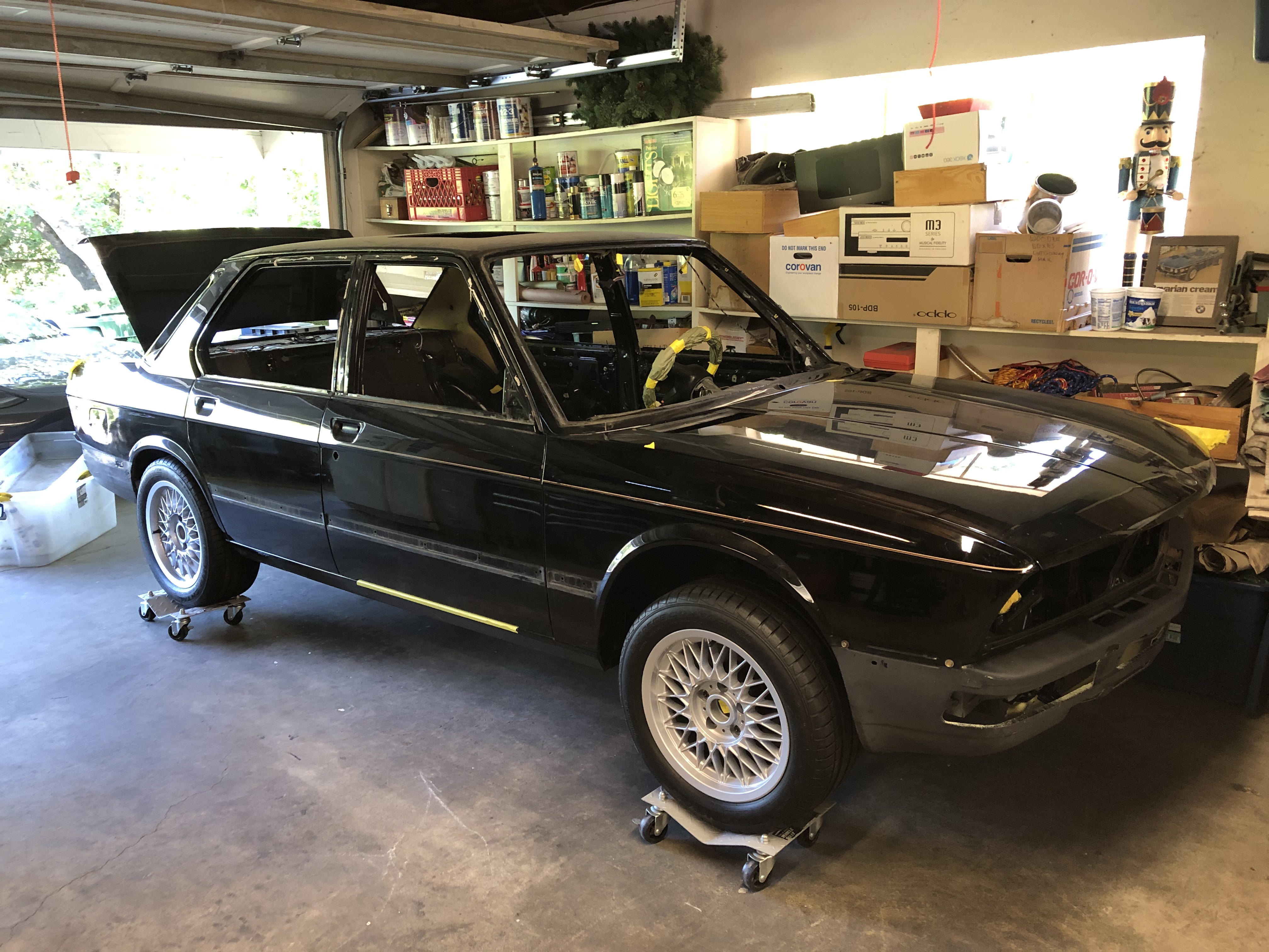
For now, I've found at least three shops that have at least some interest in the painting project. I wish I'd started on talking to them sooner ... no surprise, but it's taking a fair amount of time to get them to come out & look at the car, get an estimate, etc. Given all the time I've recently been able to put into the project, the March 2021 completion date was actually starting to look doable, but now it feels more like the painting part will take a lot longer than I'd hoped.
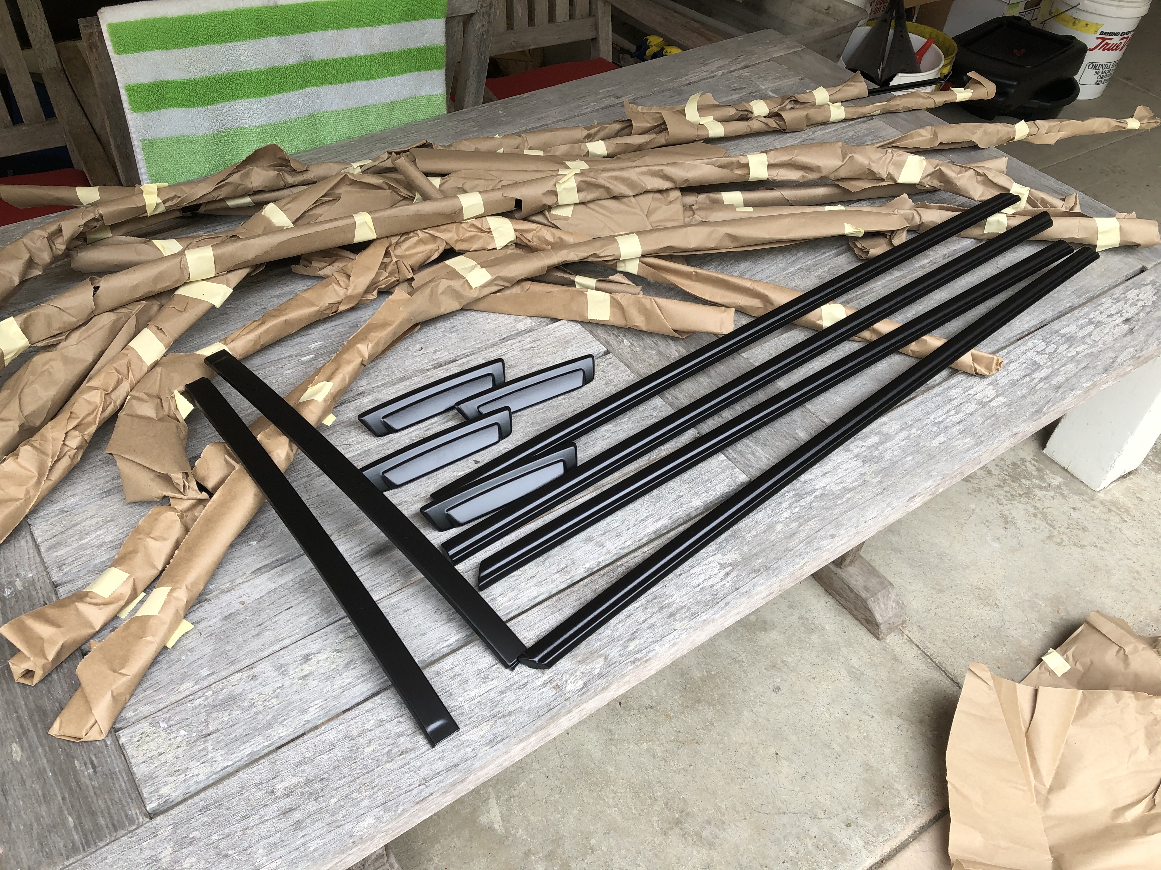
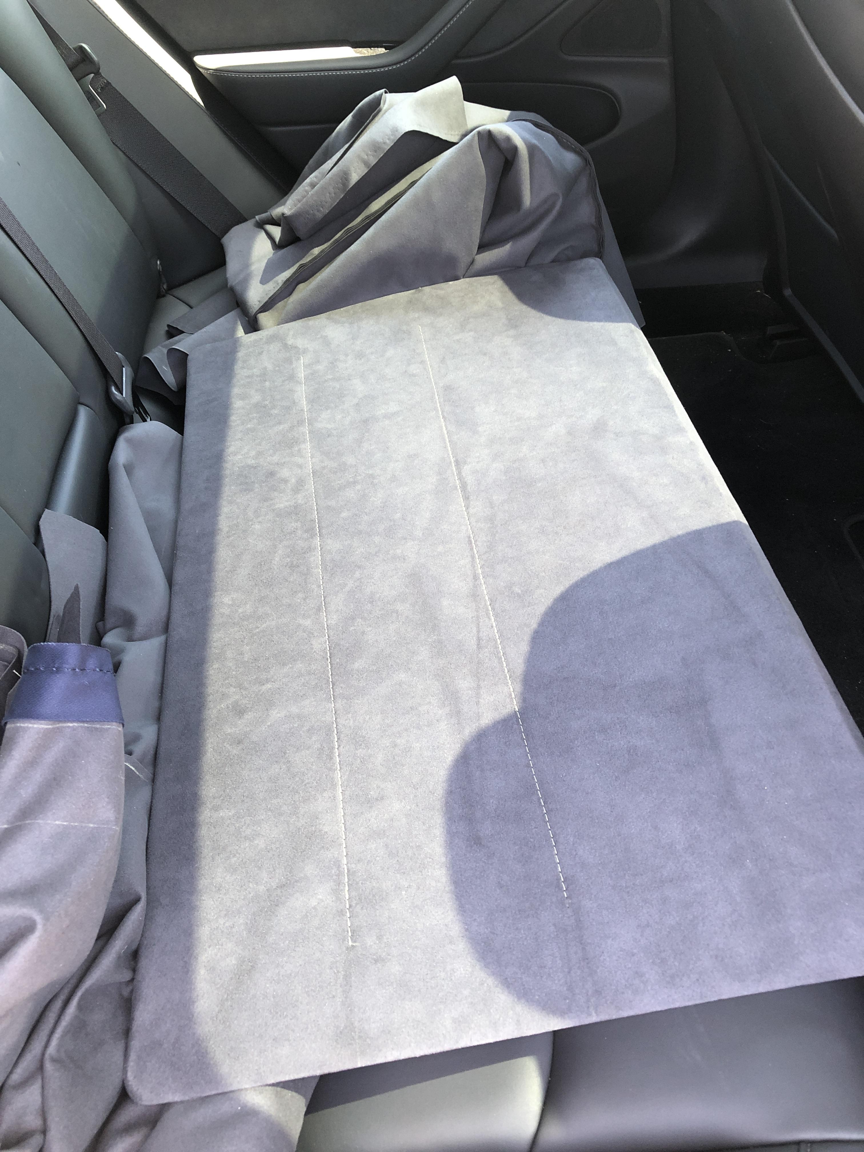
In other news, I got a few more parts back from powder coating & upholstery. (Sunroof slider is pictured below.)
I've also made some progress on converting the engine harness & management over to Motronic 1.3. Specifically, the hope is to preserve the existing S38 harness as much as possible. Grossly oversimplifying here, I'm looking to essentially put the M1.3 components at one end of the harness and the M1.3 ECU at the other end. That latter step will require converting the old harness from a 35-pin ECU connector to a 55-pin. As luck would have it, the actual wire terminal ends are pretty much identical between the 35-pin and 55-pin connectors, so I'd assumed that in theory I ought to be able to de-pin the 35 and re-pin the terminals into the 55. Easier said than done.
De-pinning the 35 was easy-peasy:
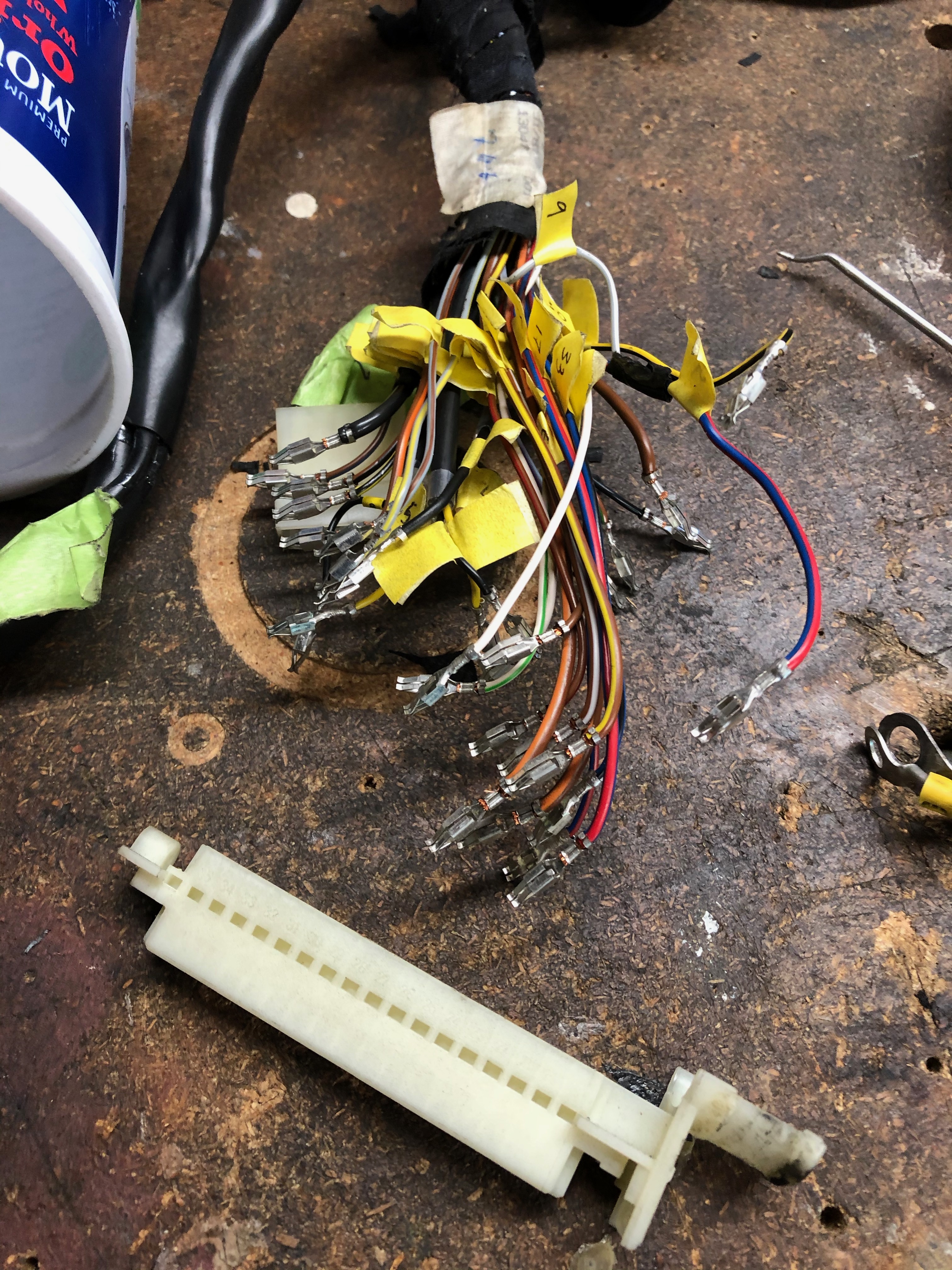
... but there 55-pin is designed a bit differently. In particular, each wire & terminal is threaded through a both a guide board and a "gate" board of some sort. Those holes on those two parts are lined up in such a way that even if you try to de-pin the catch on the terminal, you can't pull the wire out. Instead, you have to separate / delaminate the guide & gate from the actual terminal board, and then de-pin the connections. This was a total PIA and I spent an entire evening trying to figure this out, and basically ruined the 55-pin parts in the process:
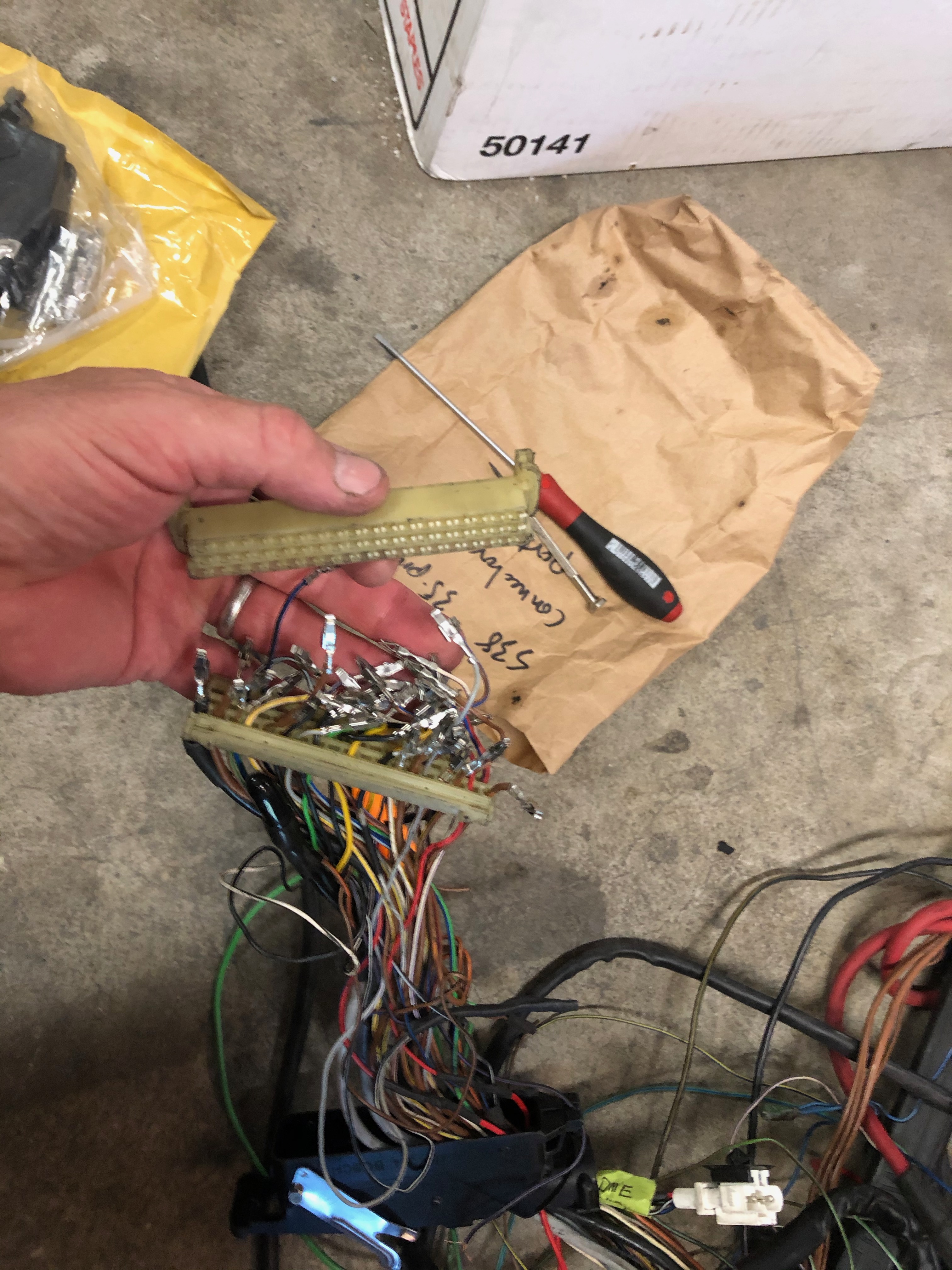
Luckily, I've been planning for the wiring project for a while, so I've been collecting extra M1.3 harnesses & parts along the way. And then on this past Tuesday I totally lucked out. My local shop was tossing the engine harness from a first gen 750iL, and it turns out that those harness have three - THREE!! - 55-pin connectors. Now that I had some sense of what I was doing, and didn't care about the wires on these connectors, I just "shaved" the wires down, pulled off the guide & gate, and de-pinned all the terminals. Clean & easy.
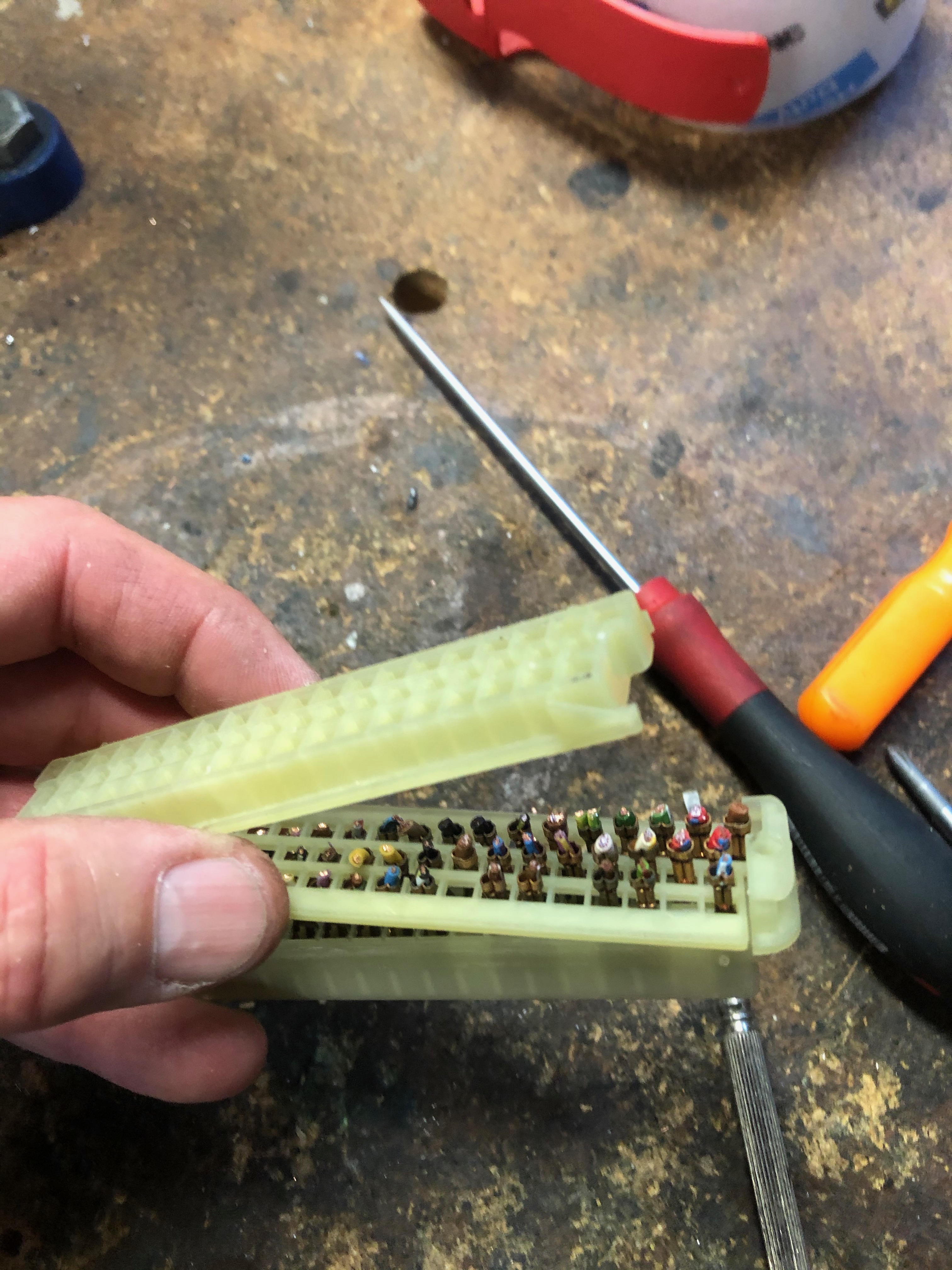
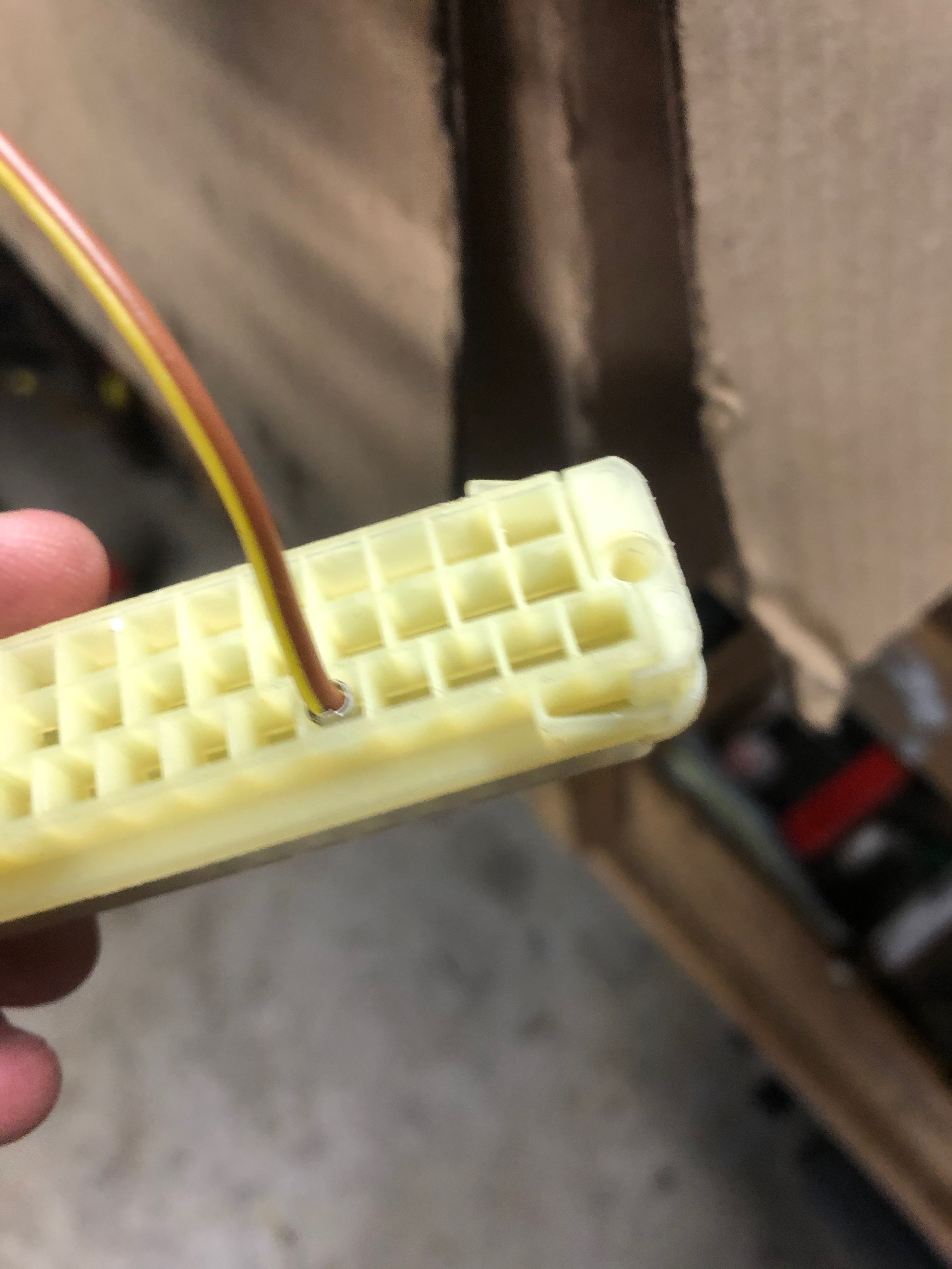
And just to confirm, I test-pinned one of the terminals from my S38 harness. Fit right in. And it's not shown here, but the terminals will lace right through the guide & gate plates as long as you do it before reassembling the three connector parts. That is, I'll need to lace all of my wires from the harness through the right holes in the guide & gate plates before doing the re-pinning.
So, after finishing the front euro bumper & valance work, I turned to assembling & reinstalling everything underneath. Rear subframe laid out in prep for reassembly:

And installed:

Fronts as well (brake caliper is there just for dry fitting):

And back down (almost) on the ground sort-of-kind-of actually looking like a car:

For now, I've found at least three shops that have at least some interest in the painting project. I wish I'd started on talking to them sooner ... no surprise, but it's taking a fair amount of time to get them to come out & look at the car, get an estimate, etc. Given all the time I've recently been able to put into the project, the March 2021 completion date was actually starting to look doable, but now it feels more like the painting part will take a lot longer than I'd hoped.
In other news, I got a few more parts back from powder coating & upholstery. (Sunroof slider is pictured below.)


I've also made some progress on converting the engine harness & management over to Motronic 1.3. Specifically, the hope is to preserve the existing S38 harness as much as possible. Grossly oversimplifying here, I'm looking to essentially put the M1.3 components at one end of the harness and the M1.3 ECU at the other end. That latter step will require converting the old harness from a 35-pin ECU connector to a 55-pin. As luck would have it, the actual wire terminal ends are pretty much identical between the 35-pin and 55-pin connectors, so I'd assumed that in theory I ought to be able to de-pin the 35 and re-pin the terminals into the 55. Easier said than done.
De-pinning the 35 was easy-peasy:

... but there 55-pin is designed a bit differently. In particular, each wire & terminal is threaded through a both a guide board and a "gate" board of some sort. Those holes on those two parts are lined up in such a way that even if you try to de-pin the catch on the terminal, you can't pull the wire out. Instead, you have to separate / delaminate the guide & gate from the actual terminal board, and then de-pin the connections. This was a total PIA and I spent an entire evening trying to figure this out, and basically ruined the 55-pin parts in the process:

Luckily, I've been planning for the wiring project for a while, so I've been collecting extra M1.3 harnesses & parts along the way. And then on this past Tuesday I totally lucked out. My local shop was tossing the engine harness from a first gen 750iL, and it turns out that those harness have three - THREE!! - 55-pin connectors. Now that I had some sense of what I was doing, and didn't care about the wires on these connectors, I just "shaved" the wires down, pulled off the guide & gate, and de-pinned all the terminals. Clean & easy.

And just to confirm, I test-pinned one of the terminals from my S38 harness. Fit right in. And it's not shown here, but the terminals will lace right through the guide & gate plates as long as you do it before reassembling the three connector parts. That is, I'll need to lace all of my wires from the harness through the right holes in the guide & gate plates before doing the re-pinning.

Re: Rebuilding My 1988 US-spec M5
Incredible work, Sir. Incredible.
Re: Rebuilding My 1988 US-spec M5
Made some significant progress today! First some background. As mentioned earlier, I've been planning on getting the car fully repainted, and towards that end I've been talking to a couple of body & paint places recently. The cost estimates so far have been about what I was expecting - or even a bit on the low end. Body shops are suffering as much as everyone else, and this is a decent job if the insurance companies aren't sending you a ton of work.
But then, in talking about my experience with a buddy who's in the biz, he mentioned that I ought to go talk to a local guy who's more in the full restoration biz. As luck would have it, the guy (Roger) has a shop just down the road from me and literally a stone's throw from my storage unit. It turns out this guy has been doing some pretty high-end restoration work by himself in a 4-bay shop he also built by himself. We hit it off pretty well, and he came to take a careful look at my car. His advice? "Don't paint it!" He ran the paint meter all around the car. Except for one spot that likely has some filler (and it's also looking like the hood has been repainted, but we're not sure on that yet), the paint is all original. So after batting it around for a couple hours, his suggested strategy is:
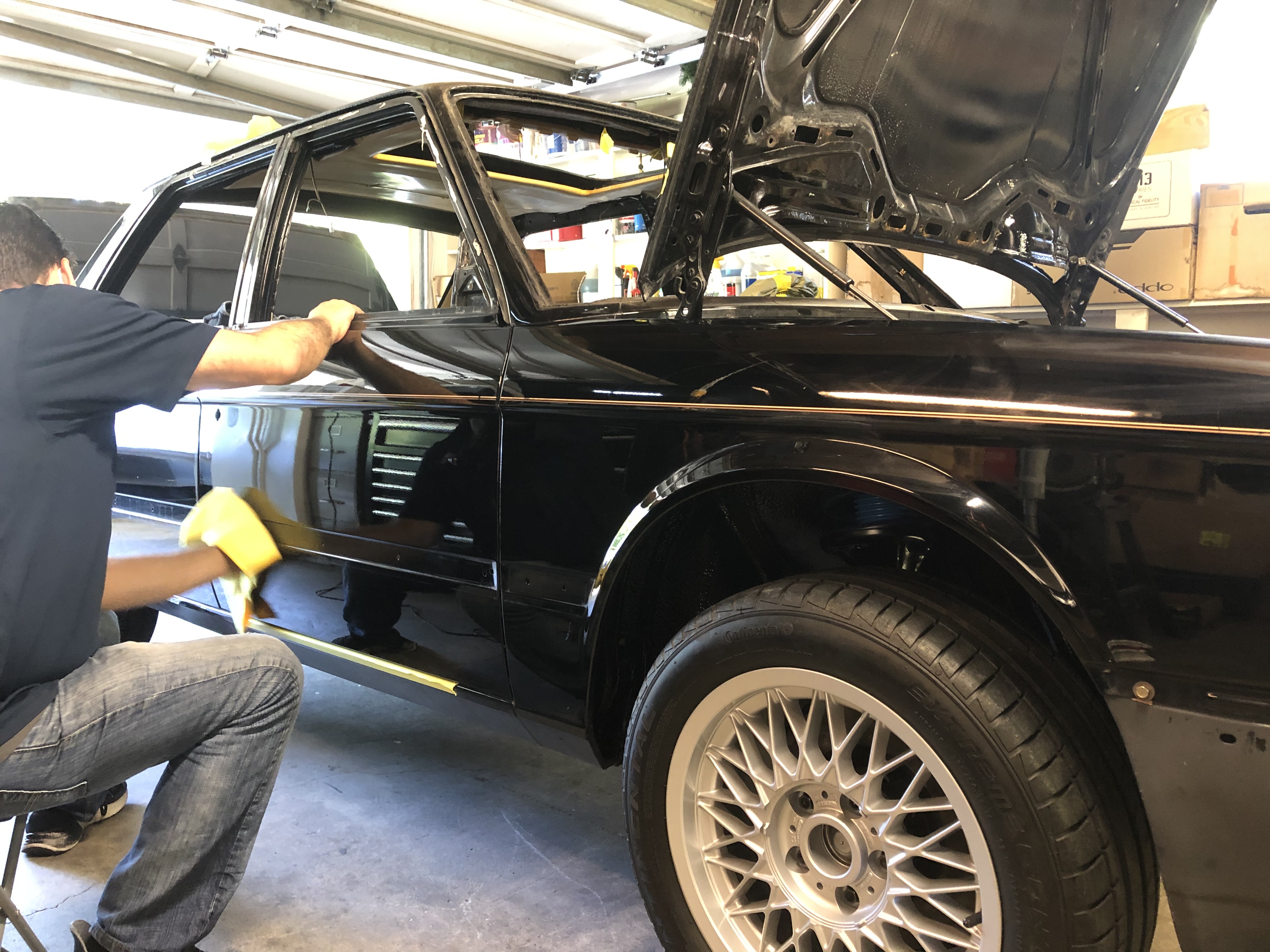
So, after getting a referral, I lined up a good dent guy. Four hours in the garage and I'm amazed. There's more to do, but I'll try to give a sense of his work. Of course, in keeping with the fact that I can't properly photo-document any of this stuff for shit, I'm not sure if this will really give a proper sense of the improvement here.
Example of a door-ding before (actually, this was taken after the guy had done his first few probes, but it gives you a sense):
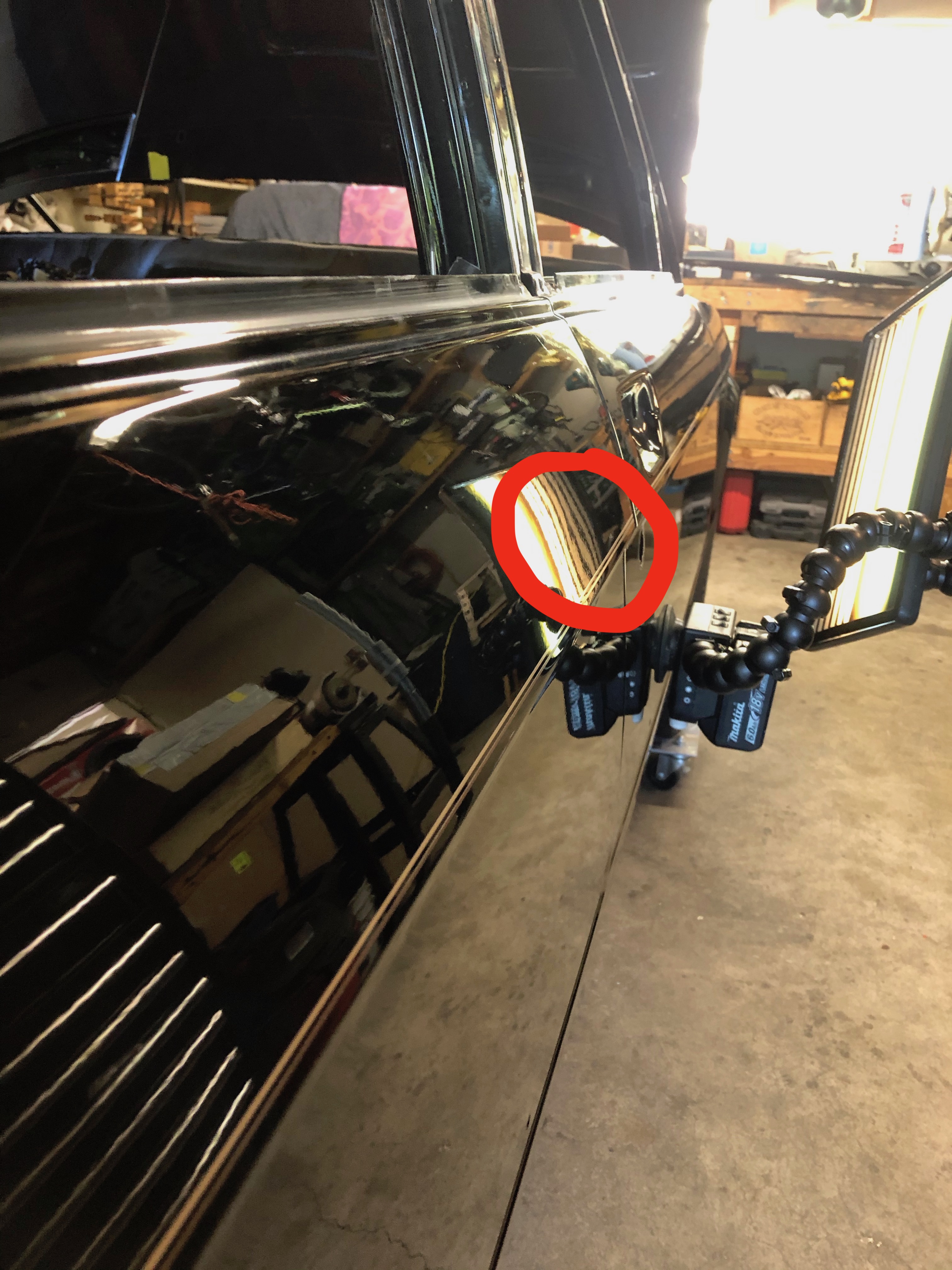
After:
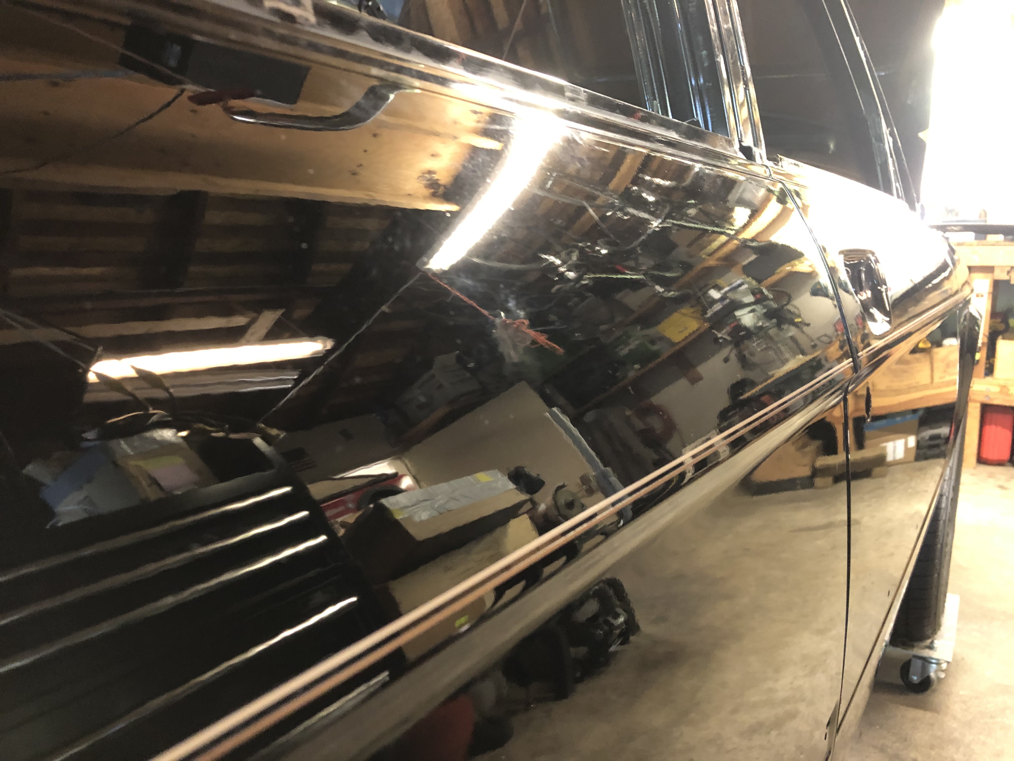
In action:
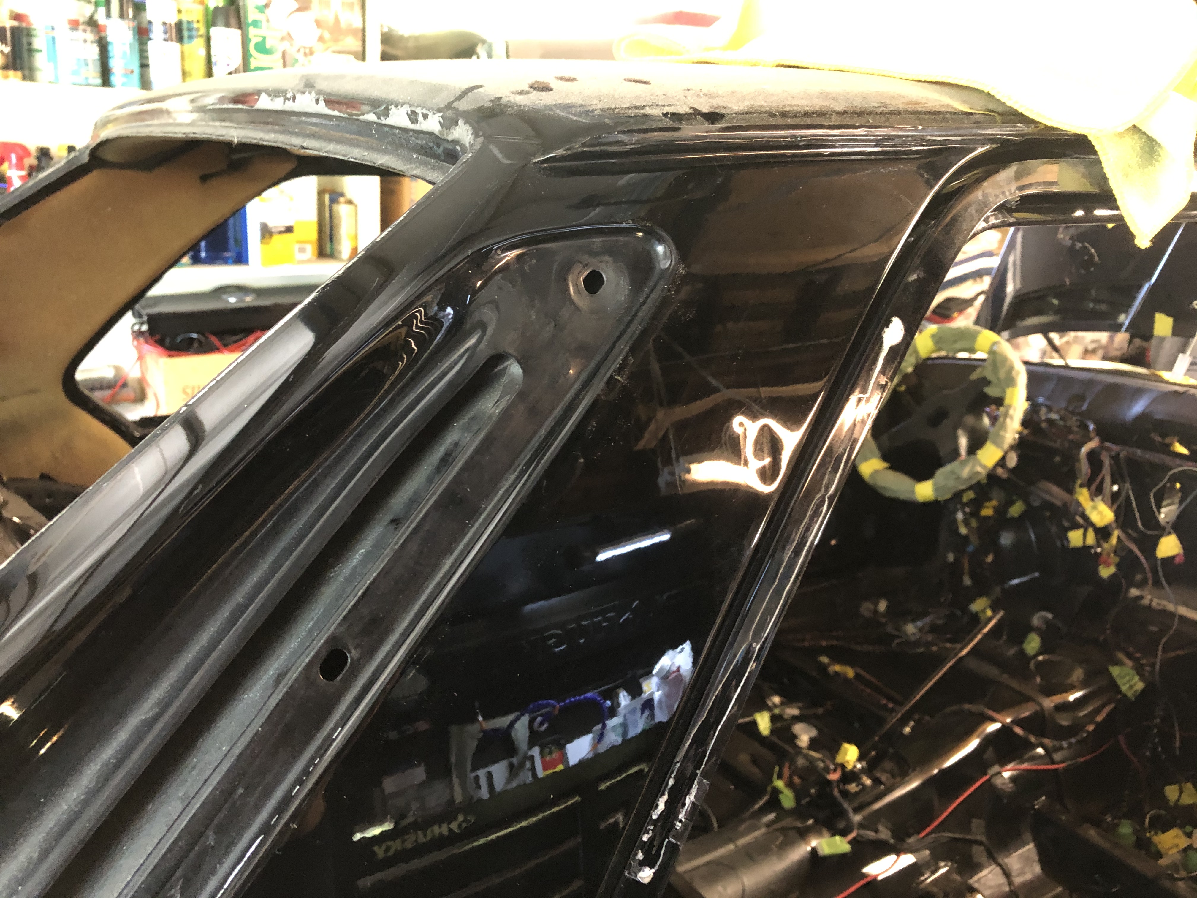
And here's the worst ding. Getting to the back of this one will be a puzzle. I haven't pulled the foam padding off from the inside of the C-pillar, but it's feeling like there's at least one more layer of sheet metal right behind this.
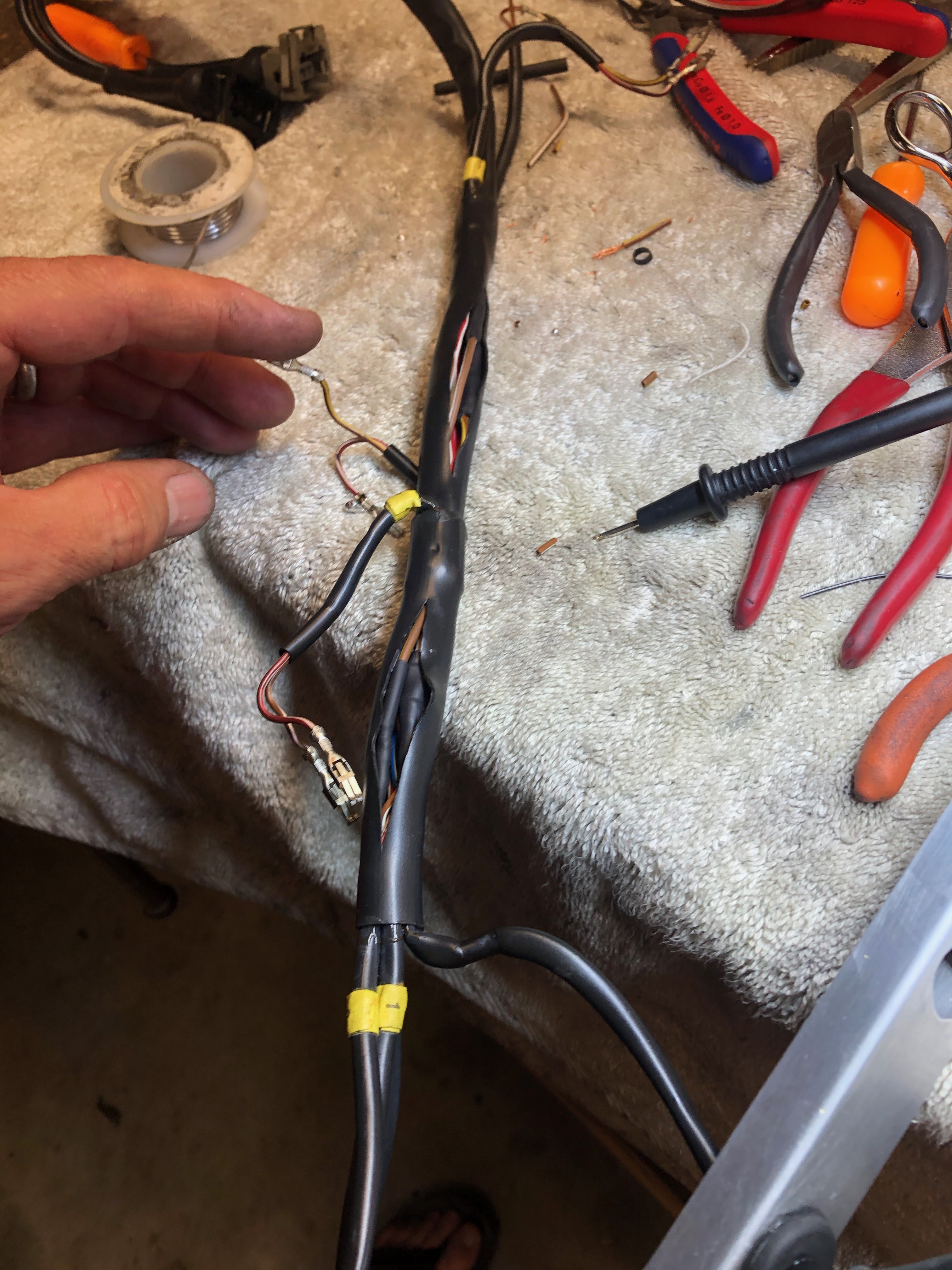
In other news, I'm aking progress on the Motronic 1.3 conversion. I'm hoping to post some specifics here (and in particular, the pin-to-pin conversion when going from the 35-pin to the 55-pin ECU connector), so this update is just one small detail: In mapping the old pins to the new pins, I noticed that both M1.0 and M1.1 fire the injectors in two banks in the following sequence: 1-2-3 then 4-5-6. But M1.3 fires them 1-3-5 then 2-4-6. I'm not sure why they made that change (one of the gurus here thought it could be performance or more likely because the revised sequence helped with emissions), but I figured the best bet was to swap the #2 and #5 wires so that the new '179 ECU would fire in the sequence designed for M1.3. So, I opened up the injector wiring harness, did a little surgery, and threaded new jumper wires inside of the existing injector harness:
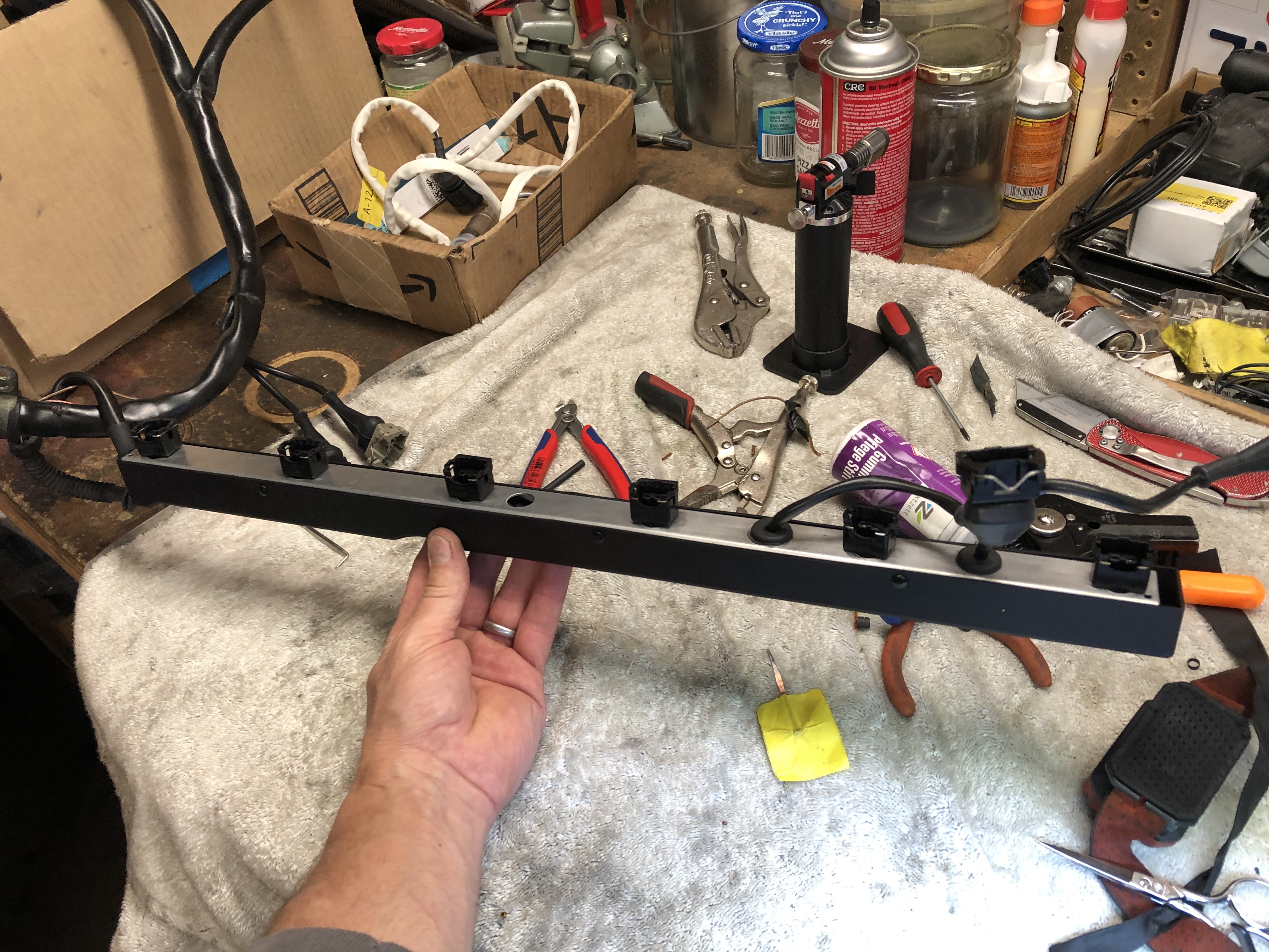
The cuts in the plastic looms were wrapped with Tessa tape before re-assembly, but naturally, I forgot to take a pic of the coolest part of the job. ¯\_(ツ)_/¯
But then, in talking about my experience with a buddy who's in the biz, he mentioned that I ought to go talk to a local guy who's more in the full restoration biz. As luck would have it, the guy (Roger) has a shop just down the road from me and literally a stone's throw from my storage unit. It turns out this guy has been doing some pretty high-end restoration work by himself in a 4-bay shop he also built by himself. We hit it off pretty well, and he came to take a careful look at my car. His advice? "Don't paint it!" He ran the paint meter all around the car. Except for one spot that likely has some filler (and it's also looking like the hood has been repainted, but we're not sure on that yet), the paint is all original. So after batting it around for a couple hours, his suggested strategy is:
- Get a good "pointless" dent repair guy to fix all the little dings & such above the "schutz line"
- Get the car trailered to Roger's shop
- Do the required metal work below the schutz line (welded in holes from US bumper light wires, repairs to rockers, etc.)
- Re-schutz and re-paint.
So, after getting a referral, I lined up a good dent guy. Four hours in the garage and I'm amazed. There's more to do, but I'll try to give a sense of his work. Of course, in keeping with the fact that I can't properly photo-document any of this stuff for shit, I'm not sure if this will really give a proper sense of the improvement here.
Example of a door-ding before (actually, this was taken after the guy had done his first few probes, but it gives you a sense):

After:

In action:

And here's the worst ding. Getting to the back of this one will be a puzzle. I haven't pulled the foam padding off from the inside of the C-pillar, but it's feeling like there's at least one more layer of sheet metal right behind this.

In other news, I'm aking progress on the Motronic 1.3 conversion. I'm hoping to post some specifics here (and in particular, the pin-to-pin conversion when going from the 35-pin to the 55-pin ECU connector), so this update is just one small detail: In mapping the old pins to the new pins, I noticed that both M1.0 and M1.1 fire the injectors in two banks in the following sequence: 1-2-3 then 4-5-6. But M1.3 fires them 1-3-5 then 2-4-6. I'm not sure why they made that change (one of the gurus here thought it could be performance or more likely because the revised sequence helped with emissions), but I figured the best bet was to swap the #2 and #5 wires so that the new '179 ECU would fire in the sequence designed for M1.3. So, I opened up the injector wiring harness, did a little surgery, and threaded new jumper wires inside of the existing injector harness:


The cuts in the plastic looms were wrapped with Tessa tape before re-assembly, but naturally, I forgot to take a pic of the coolest part of the job. ¯\_(ツ)_/¯
Re: Rebuilding My 1988 US-spec M5
I view the not needing to paint as HUGE news. Congrats on that. I like Roger.
Re: Rebuilding My 1988 US-spec M5
Do you know Roger? Man, you seem to know everyone.cek wrote: Jun 02, 2020 8:57 PM I view the not needing to paint as HUGE news. Congrats on that. I like Roger.
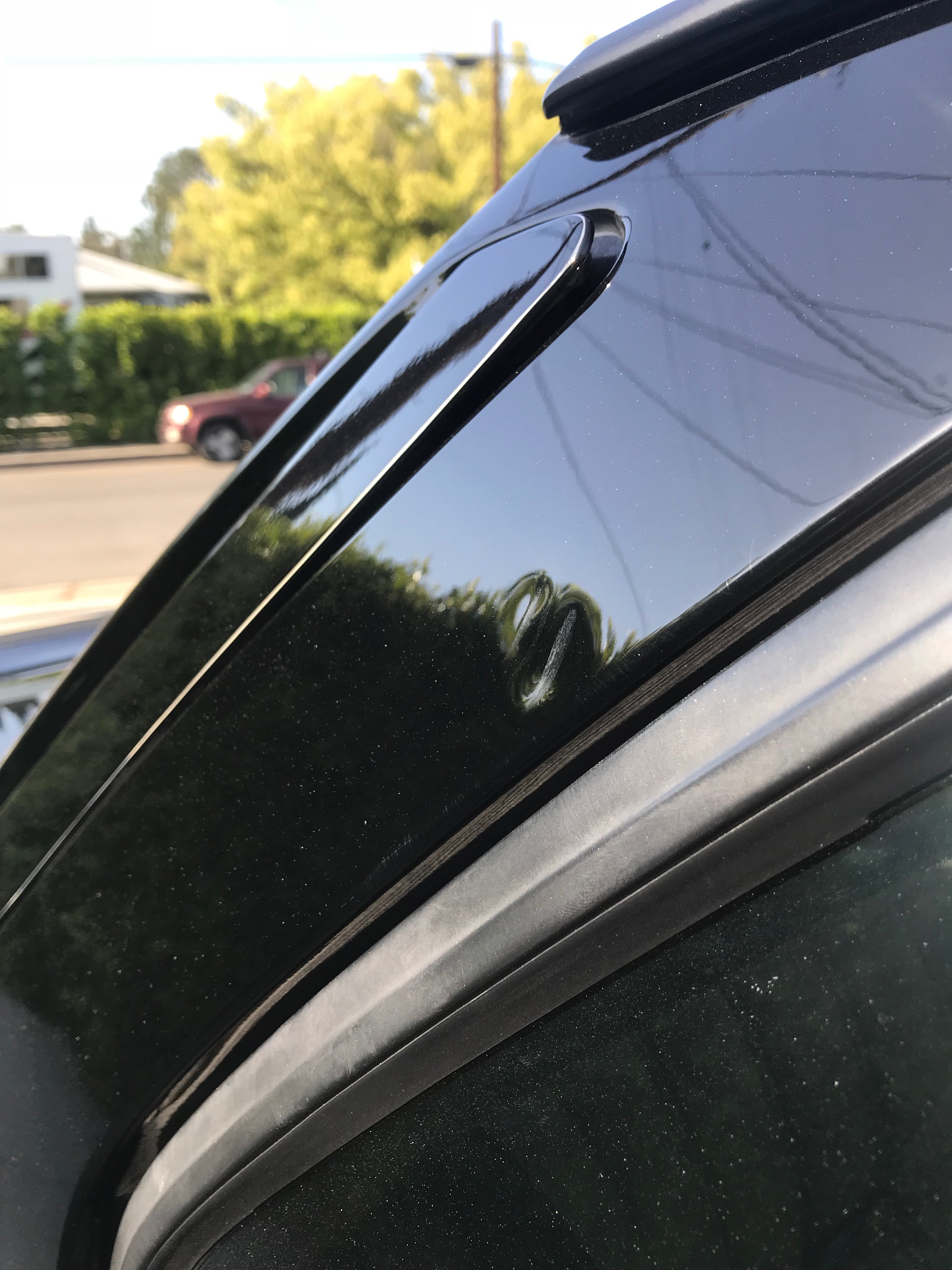
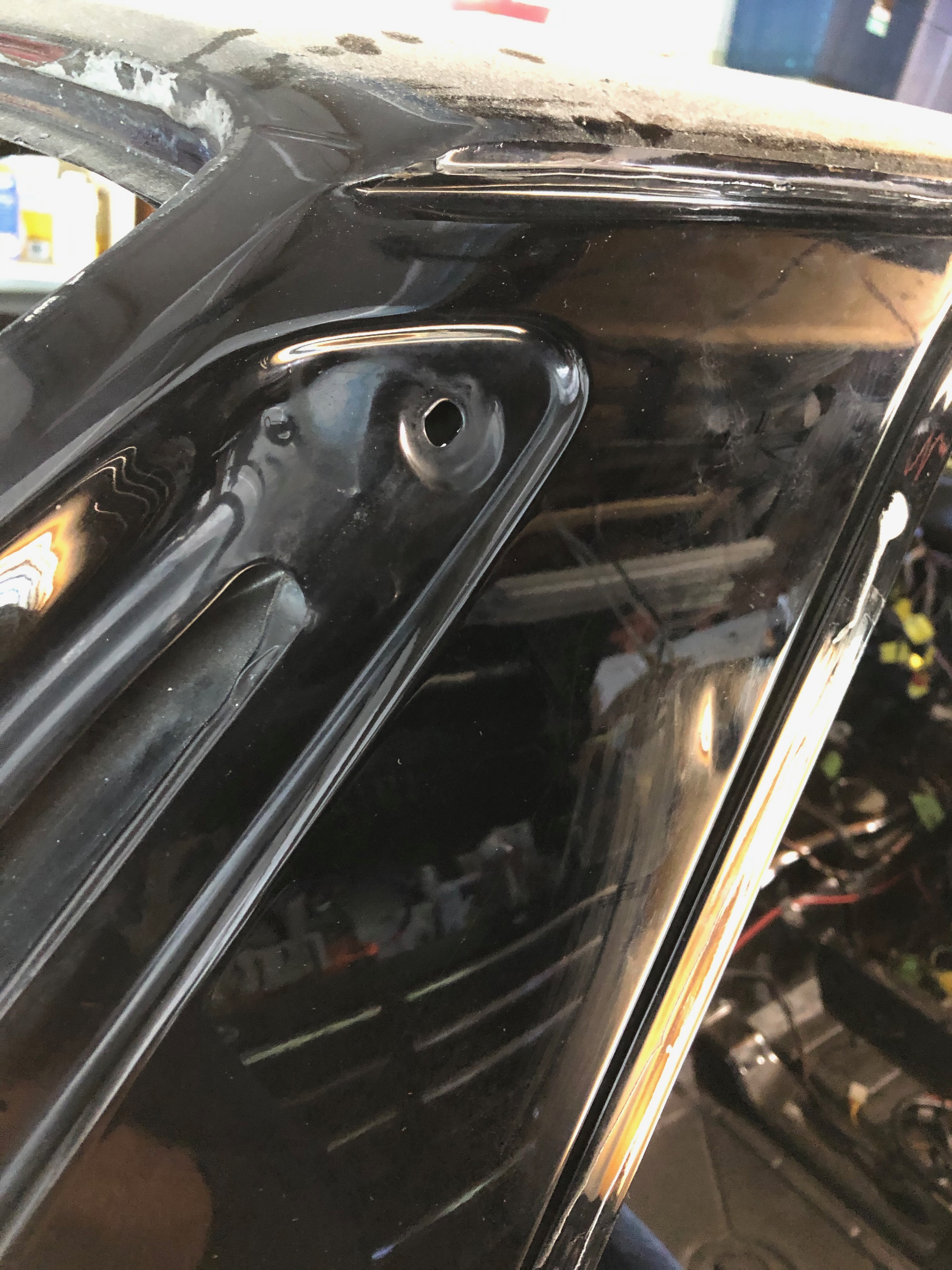
Anyhow, my dent guy is back today. I'm stunned by the results he's getting. Here's a visual on his progress on that C-pillar dent. Remember, there's no way to directly access the backside of this dent because there are multiple layers of metal in that part of the C-pillar. So, this improvement (so far) is almost all due to working from the front.
"Before" (one from before the car was disassembled and one from Tuesday):

And currently (the haze is from a waxy polish he's using to protect the paint):
Re: Rebuilding My 1988 US-spec M5
OK, so I know I'm obsessing too much on this one small section of the car, but I'm fascinated by what this guy has done with his bag of tricks to pull a dent that I thought for sure was going to have to get filled & repainted. Here's his final product:
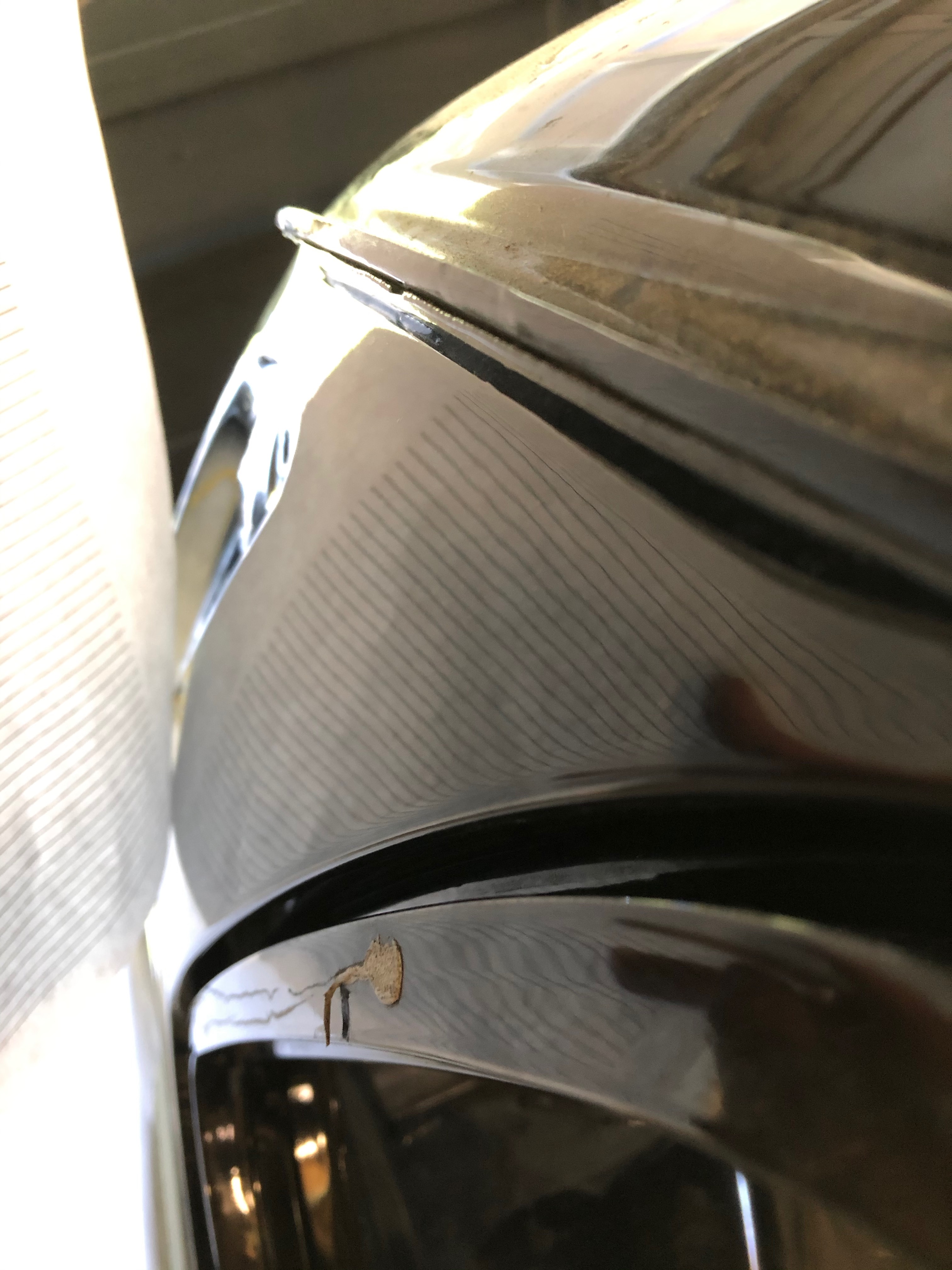
I have to admit that this camera angle is sort of a cheat; the light in the garage is pretty bad and this was one of the few angles that clearly shows the fixed area with a nice clear reflection of the repair. With the naked eye, the area still shows remnants of the repair. Regardless, I feel like I've found a brand new tool!

I have to admit that this camera angle is sort of a cheat; the light in the garage is pretty bad and this was one of the few angles that clearly shows the fixed area with a nice clear reflection of the repair. With the naked eye, the area still shows remnants of the repair. Regardless, I feel like I've found a brand new tool!
Re: Rebuilding My 1988 US-spec M5
Quick update: The restoration shop nearby should be ready for the whole car next week (fingers crossed). The hood has already been delivered:
I was at the shop over the weekend, and Roger had already done a fair amount of work on the top side of the hood. We had been worked that the hood had been painted at some point, but Roger's paint meter said, "Nope, original paint." The improvement that Roger had made with just a coupe hours work was pretty amazing. Of course, we got to talking ... and I forgot to take pics. Next time.
In other news, I'm continuing to collect bits and parts for the motor, including getting a bunch more parts back from the zinc plating shop. The local shop I'm using in San Leandro has a brand new zinc plating line ... the result so far have been amazing. Here's a before and after on the alternator.
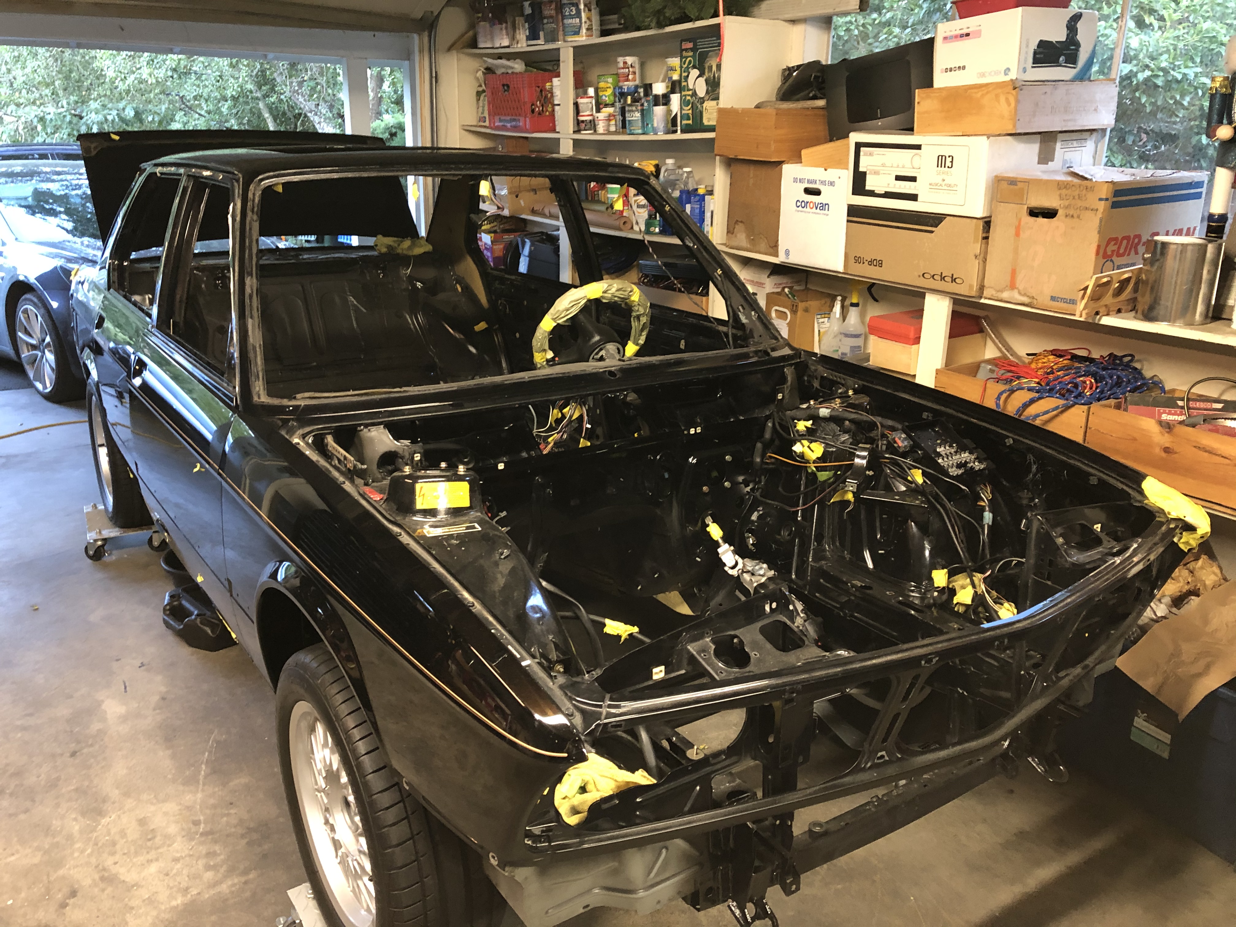
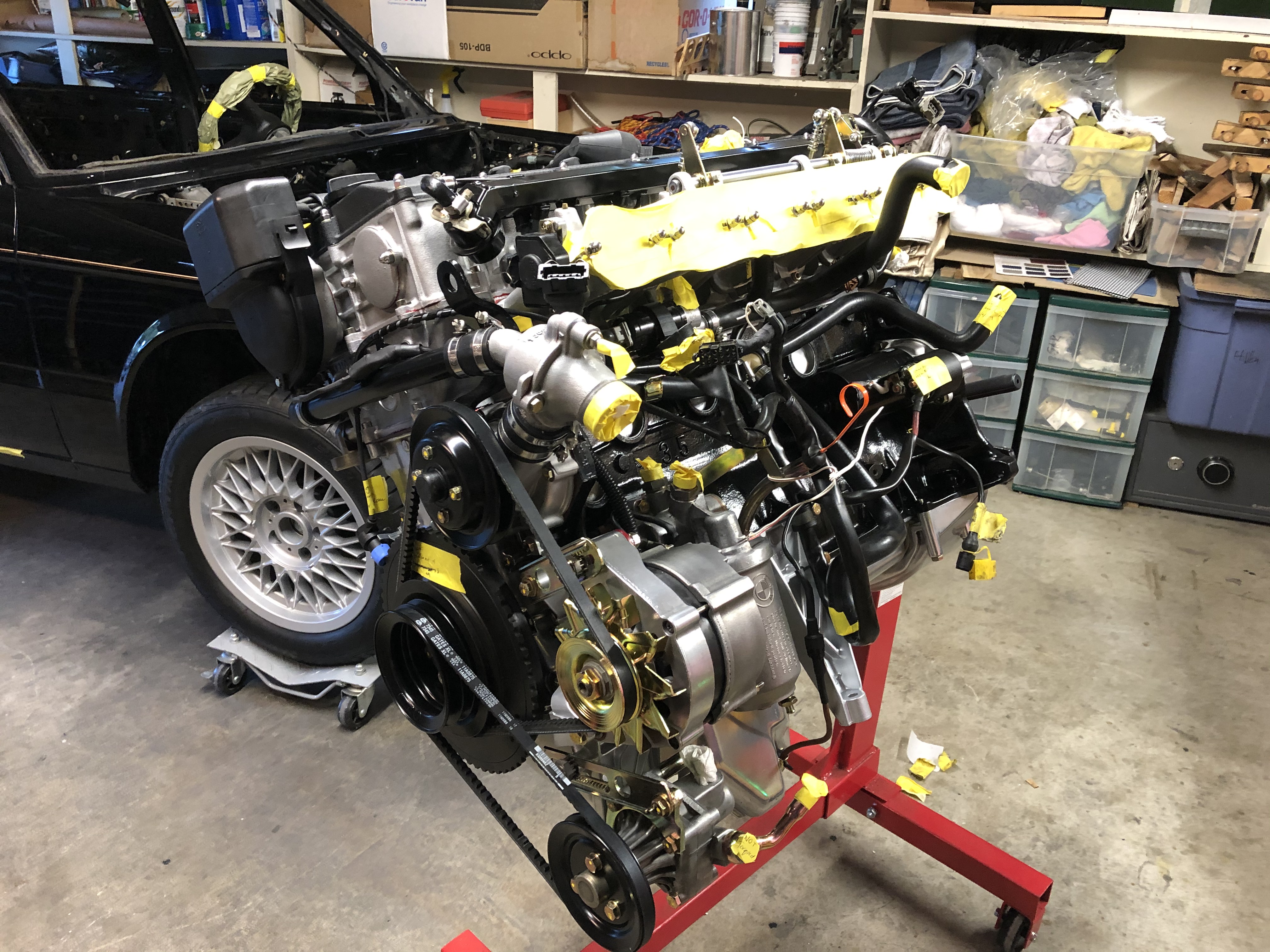
Here's the current status on the motor. With the accessories slowly going on, it seemed like the right time to start fitting the engine wiring harness back on.
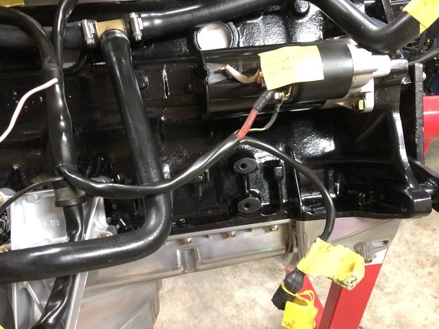
Next step will be to splice in a new 4-wire O2 connector and fab a new mounting bracket that will hold the O2 sensor-to-harness connector plus hold the other wires that snake down from the lower left block to the underside of the car.

I was at the shop over the weekend, and Roger had already done a fair amount of work on the top side of the hood. We had been worked that the hood had been painted at some point, but Roger's paint meter said, "Nope, original paint." The improvement that Roger had made with just a coupe hours work was pretty amazing. Of course, we got to talking ... and I forgot to take pics. Next time.
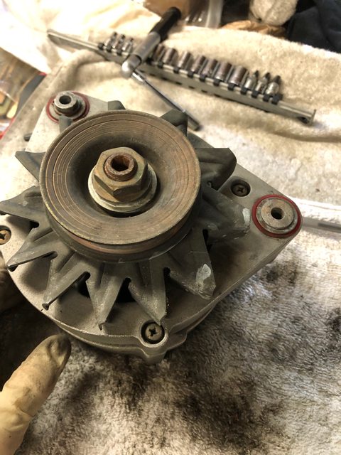
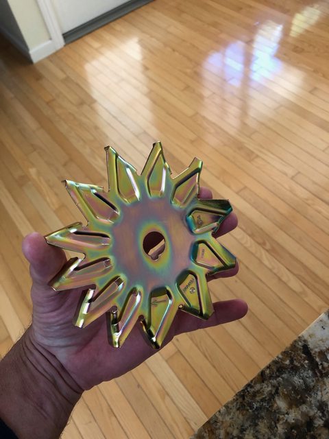
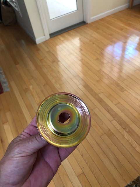
In other news, I'm continuing to collect bits and parts for the motor, including getting a bunch more parts back from the zinc plating shop. The local shop I'm using in San Leandro has a brand new zinc plating line ... the result so far have been amazing. Here's a before and after on the alternator.


Here's the current status on the motor. With the accessories slowly going on, it seemed like the right time to start fitting the engine wiring harness back on.

Next step will be to splice in a new 4-wire O2 connector and fab a new mounting bracket that will hold the O2 sensor-to-harness connector plus hold the other wires that snake down from the lower left block to the underside of the car.

Re: Rebuilding My 1988 US-spec M5
Making slow progress. The "slow" part is a bit frustrating, I guess ... given that I'm working from home, I have plenty of time, but parts are harder to get, and I'm at a stage where I'm highly reliant on others (e.g., body & paint).
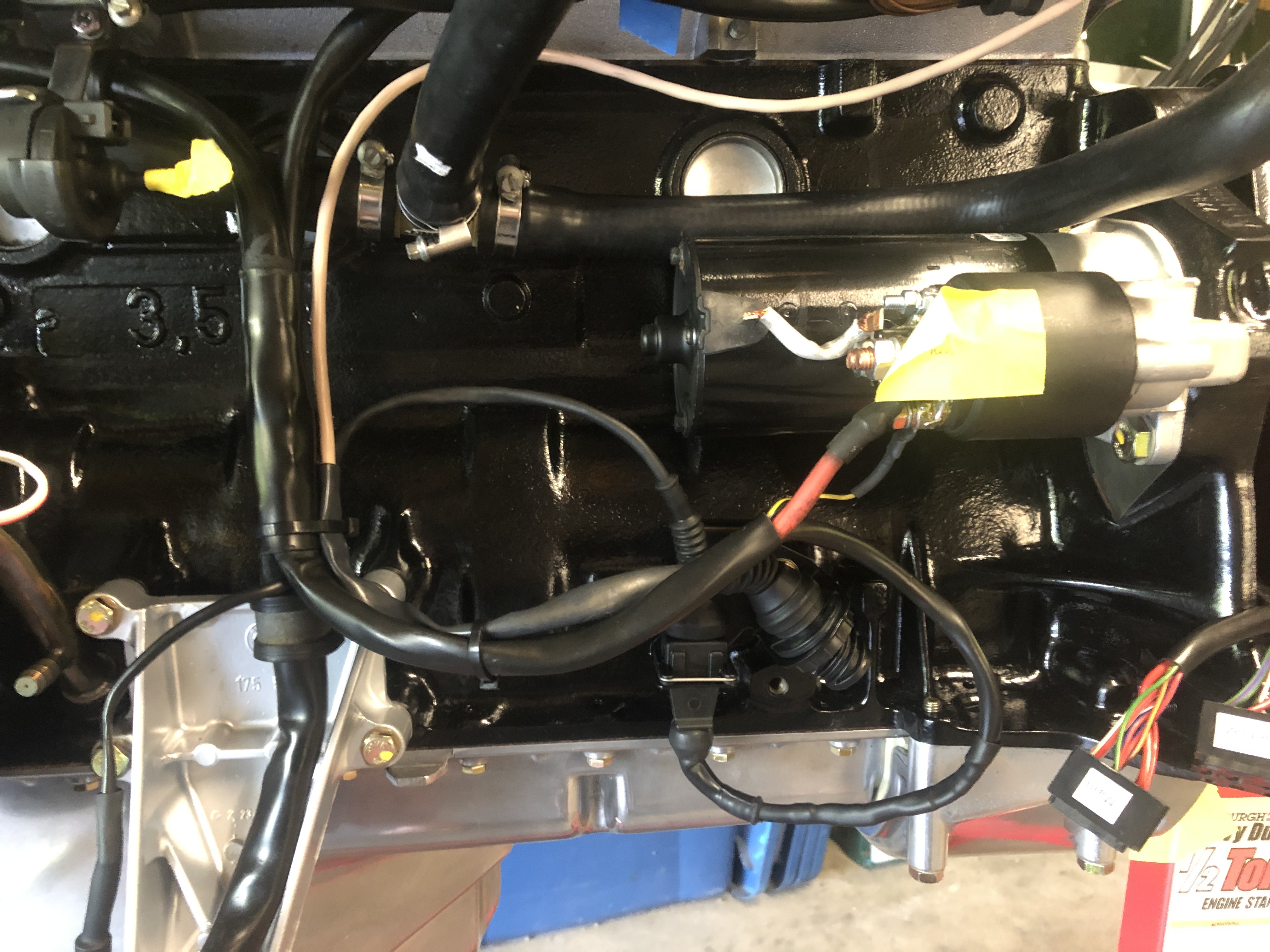
On the engine wiring, I'm mostly happy with the change-over to a 4-wire O2 sensor. I cut the 3-wire harness-side connector off, then put a 4-wire connector in. However, because the 4-wire setup has two signal wires, you can't just splice the 4-wire connector into the existing harness. Instead, I bought a length of new, 2-conductor (18 ga), shielded wire and I'm using that to carry the low voltage signal all the way from the connector to the ECU. That's the gray wire in the pic below. Since the existing engine harness is in really good shape, I obviously won't cut the original plastic loom off. It's not ideal, but the gray wire will just run parallel to the harness, run all the way through the firewall grommet and straight into the ECU. I'll be using the original wires in the existing harness for ground and the O2 sensor heater. Also, since the 4-wire connector is just a standard part on a bunch of these cars, I'm able to use the connector bracket from an M30-B35 (a bit difficult to see in this pic - it's cut off an old steel "loom" from a B35 what shields the heavy starter motor wire running from the alternator to the starter). That bracket also gives a handy spot to mount the 2-wire connector I spliced in for the ground and 12v+ lines.
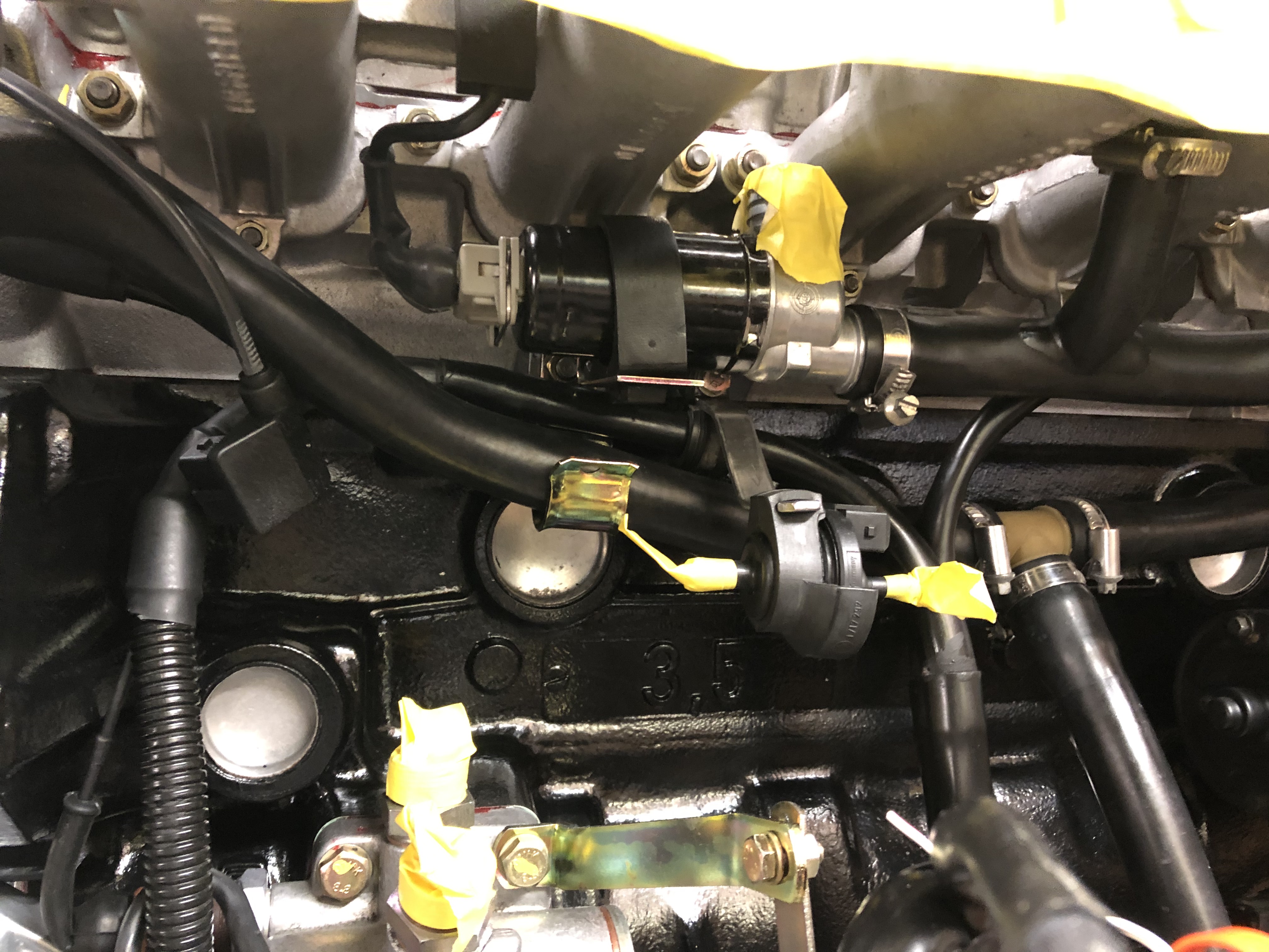
I'd also sort of hoped to re-jigger the location of the purge valve. On an M30-B35 motor running Motronic 1.3, the purge valve is mounted on the underside of the intake with the purge line running over the motor to the charcoal canister that sits front-right next to the ABS pump. I was able to fab a bracket that could hold an M1.3-style purge valve underneath the ITBs. I think it looks nice & clean, and the purge line can run from there along the original path along the front of the motor:
But if I put the purge valve in that position, then I run into the same wiring issue I have with the O2 sensor. That is, in the original harness, the purge valve wires are totally in the wrong place and run along the front-right wheel well up to the purge valve / relay / barometric pressure switch assembly that sits above the ABS pump. I can't just pull those wires out of the original plastic loom (there's a splice hidden in there somewhere), and if I just orphan them over there, then I'll need to run new wires from the M1.3 valve parallel to the existing harness, through the firewall grommet and into the ECU. That feels like too many "extra" wires outside the loom. Probably easier to just put the new purge vale in the same location as the old one. That should make it easier to pass smog as well since the location of the purge valve will match the smog diagram.
My time slot also opened up the restoration shop, so for the first time in many months the car rolled out of the garage.
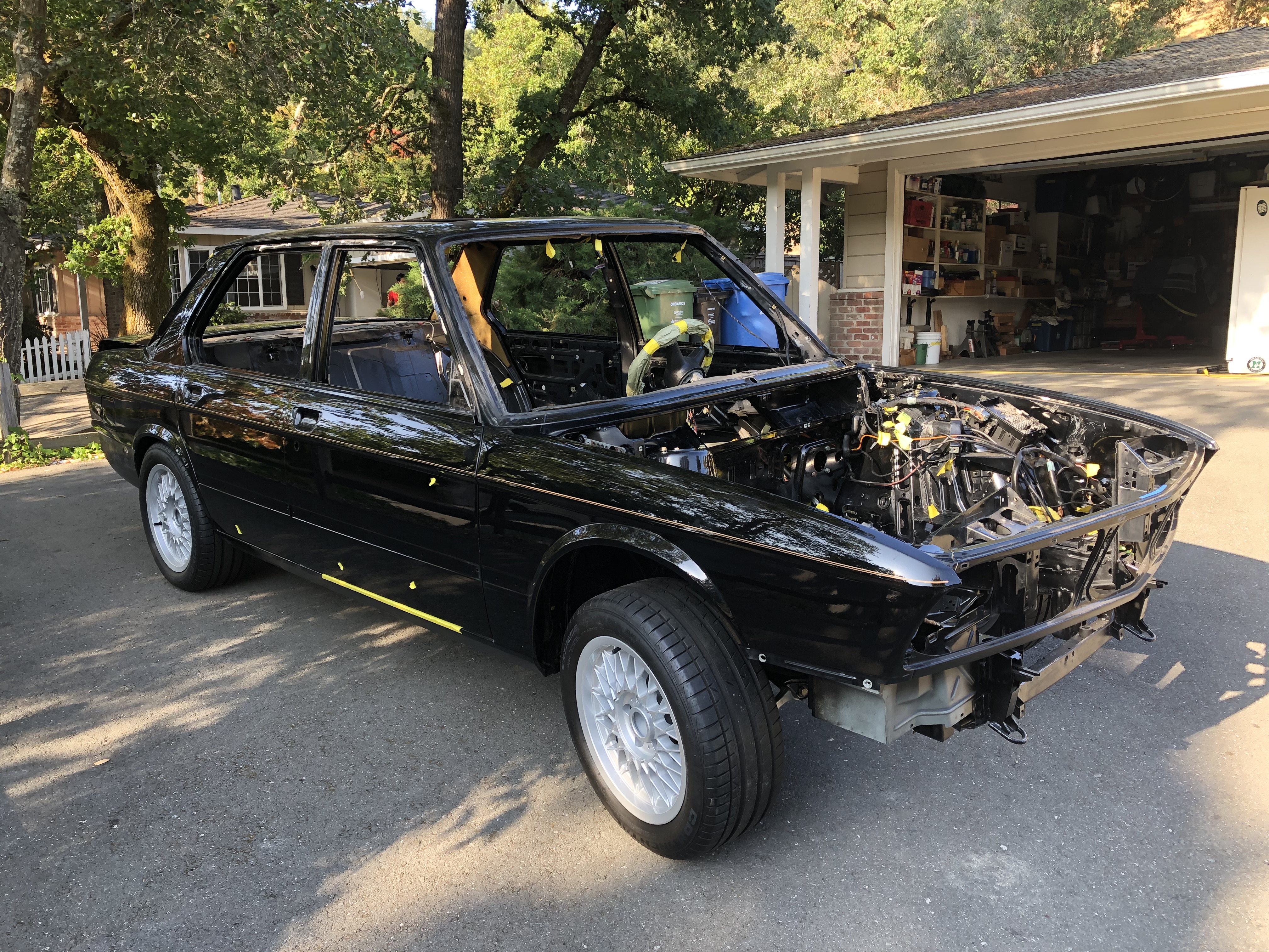
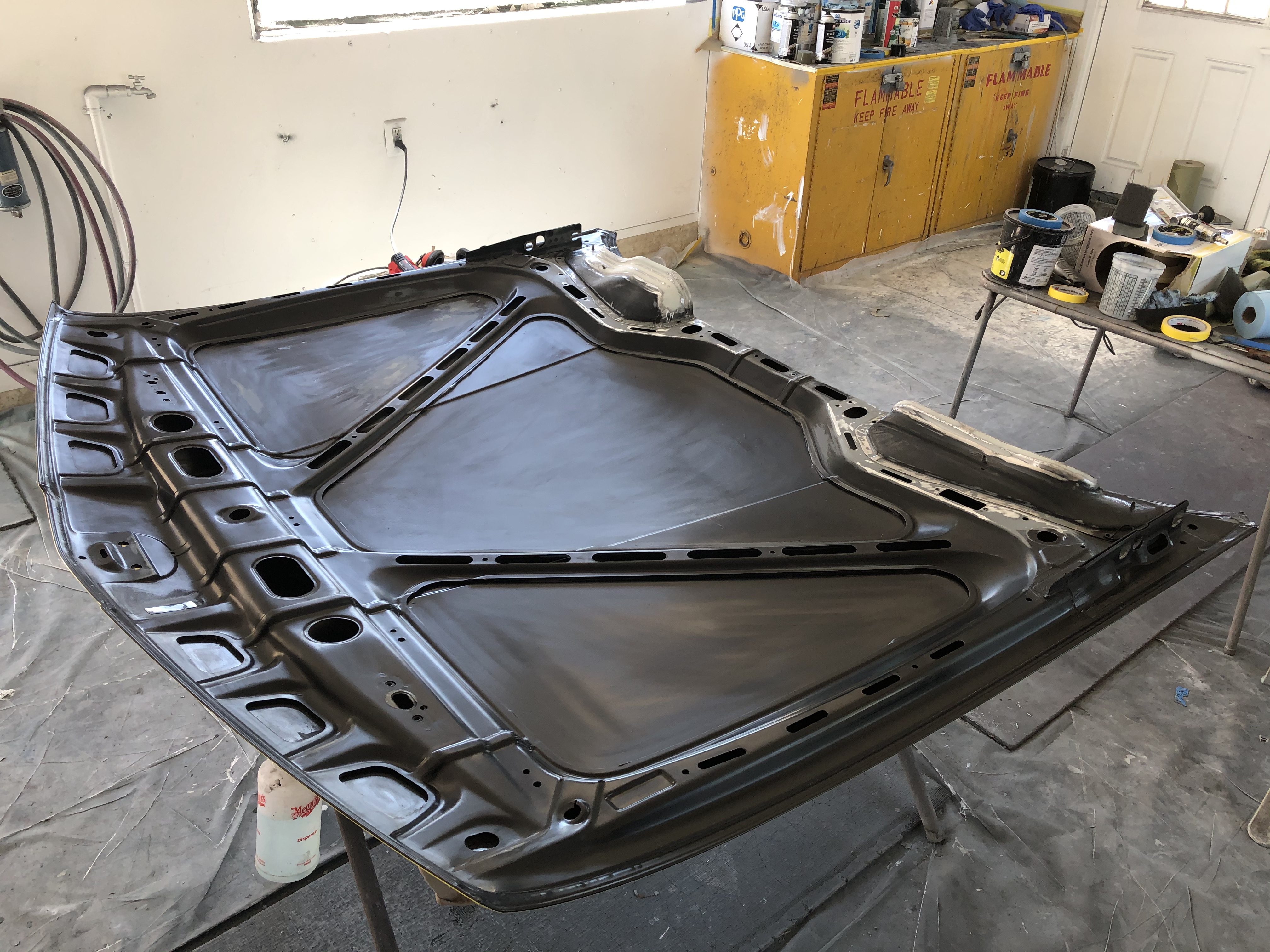
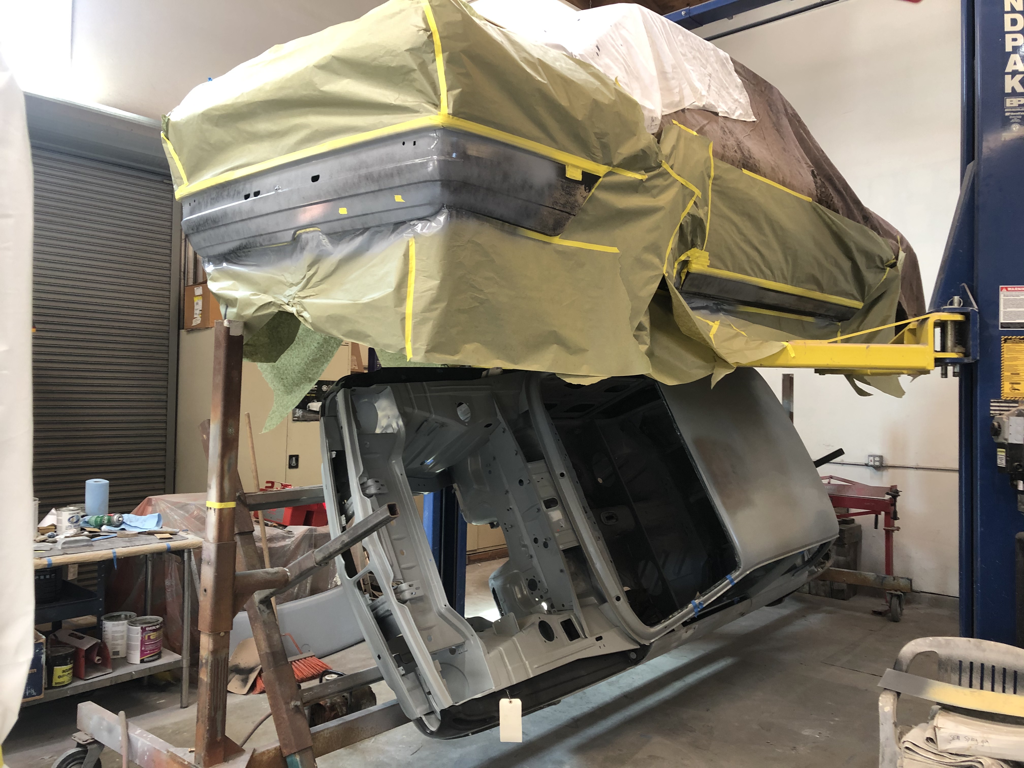
Here's some progress so far ... hood will get re-painted on the underside. You can't see it in this shot, but the top side is all original and in very good shape, so that's been polished. I forgot to get a pic before Roger covered it up, but trust me, it looks sweet.
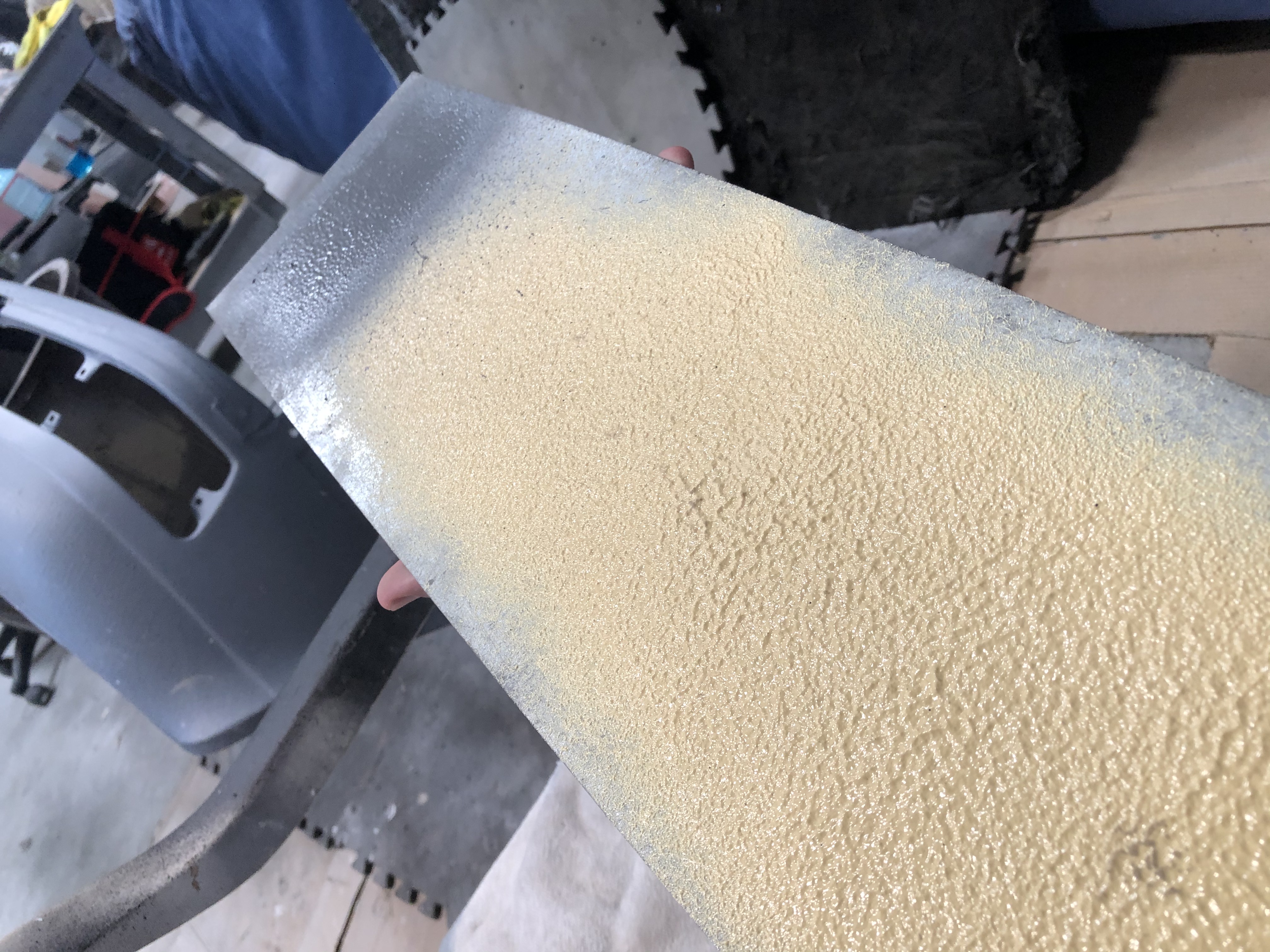
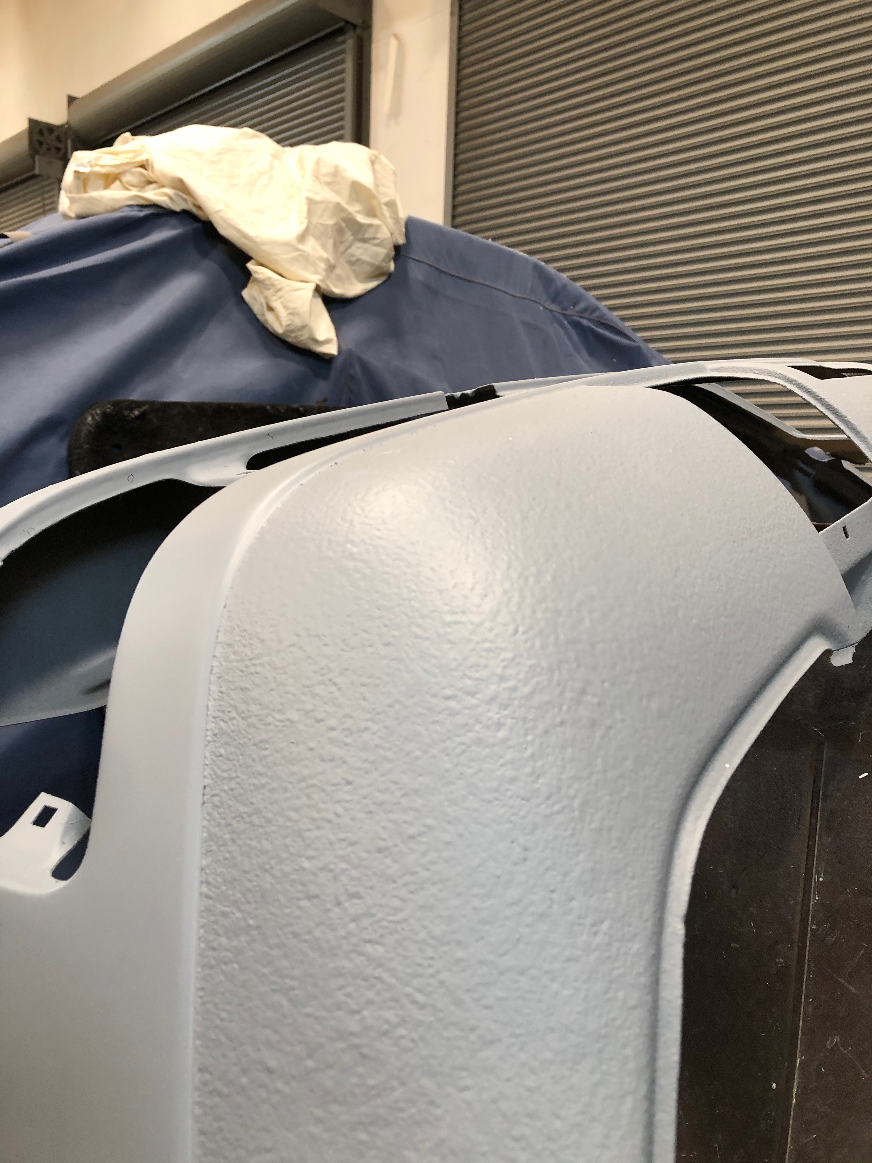
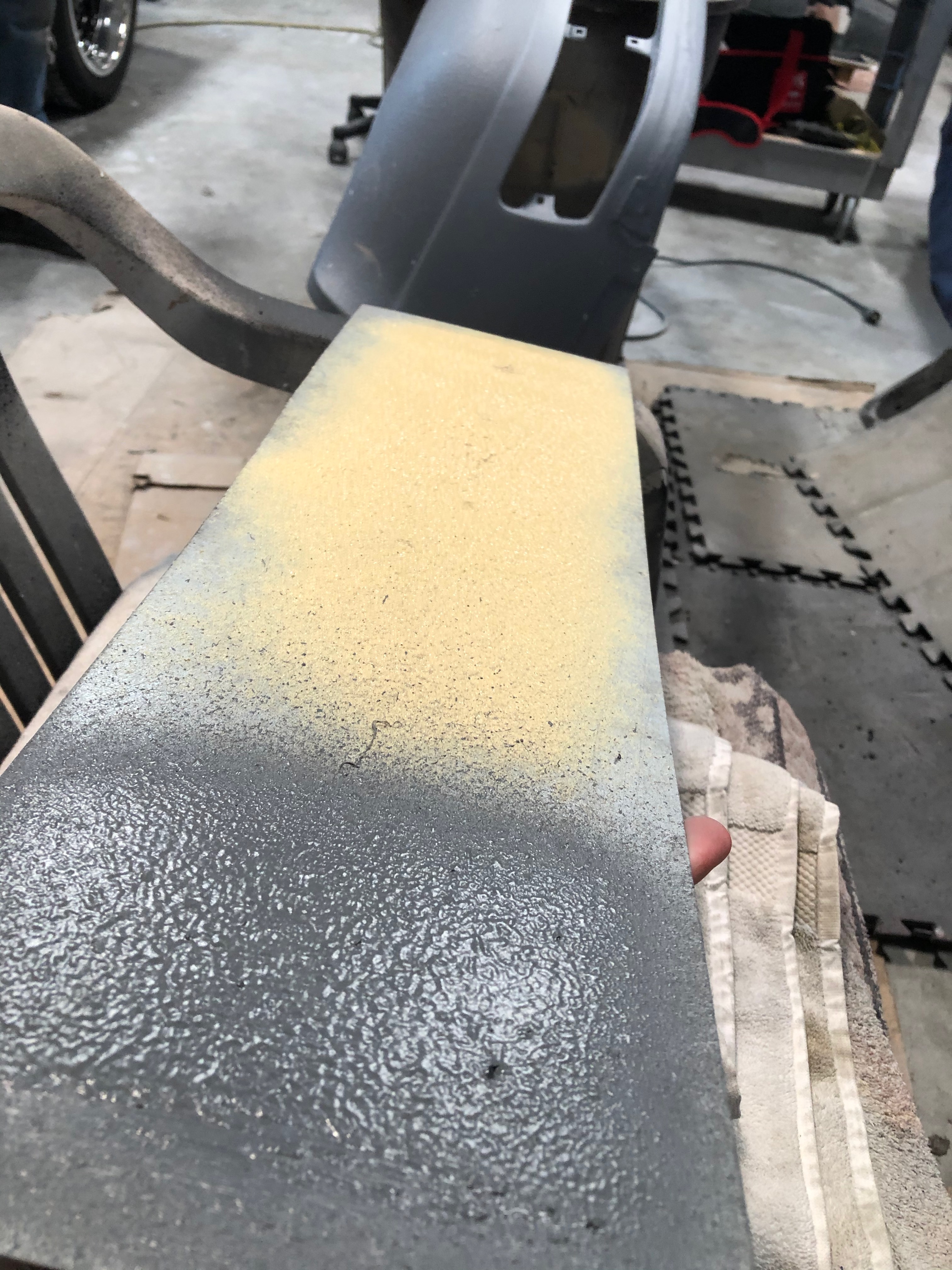
Here are shots where we're experimenting with different undercoating textures. The yellow is SEM sprayable seam sealer, the primered stuff on the front valance is a water-based coating, and the gray/black stuff next to the yellow SEM is Würth solvent-based coating. We're going to go with the Würth. Note that the glitches in that sample don't come from the coating ... apparently the gun hadn't been completely cleaned, so those glitches are from bits that had been stuck in the gun.
Exciting to see progress!
Last item for today. I have this idea that with the new euro bumpers, the large trunk spoiler from the US car will look out of proportion. One possible remedy is to get rid of the spoiler completely ... but since I definitely DON'T want to damage the existing trunk lid welding the mounting holes shut, my idea is to get a good donor lid from a car without a spoiler (e.g., a 528e), get that painted up black, and mount that on the car. That way I can keep the original trunk unmolested but also get that super-clean euro M5 look. It will likely be very tough to exactly match the black paints, but this should be a relatively cheap experiment. We'll see.
An even better solution would be to find a smaller BMW spoiler that would fit on this car. Any ideas?
On the engine wiring, I'm mostly happy with the change-over to a 4-wire O2 sensor. I cut the 3-wire harness-side connector off, then put a 4-wire connector in. However, because the 4-wire setup has two signal wires, you can't just splice the 4-wire connector into the existing harness. Instead, I bought a length of new, 2-conductor (18 ga), shielded wire and I'm using that to carry the low voltage signal all the way from the connector to the ECU. That's the gray wire in the pic below. Since the existing engine harness is in really good shape, I obviously won't cut the original plastic loom off. It's not ideal, but the gray wire will just run parallel to the harness, run all the way through the firewall grommet and straight into the ECU. I'll be using the original wires in the existing harness for ground and the O2 sensor heater. Also, since the 4-wire connector is just a standard part on a bunch of these cars, I'm able to use the connector bracket from an M30-B35 (a bit difficult to see in this pic - it's cut off an old steel "loom" from a B35 what shields the heavy starter motor wire running from the alternator to the starter). That bracket also gives a handy spot to mount the 2-wire connector I spliced in for the ground and 12v+ lines.

I'd also sort of hoped to re-jigger the location of the purge valve. On an M30-B35 motor running Motronic 1.3, the purge valve is mounted on the underside of the intake with the purge line running over the motor to the charcoal canister that sits front-right next to the ABS pump. I was able to fab a bracket that could hold an M1.3-style purge valve underneath the ITBs. I think it looks nice & clean, and the purge line can run from there along the original path along the front of the motor:

But if I put the purge valve in that position, then I run into the same wiring issue I have with the O2 sensor. That is, in the original harness, the purge valve wires are totally in the wrong place and run along the front-right wheel well up to the purge valve / relay / barometric pressure switch assembly that sits above the ABS pump. I can't just pull those wires out of the original plastic loom (there's a splice hidden in there somewhere), and if I just orphan them over there, then I'll need to run new wires from the M1.3 valve parallel to the existing harness, through the firewall grommet and into the ECU. That feels like too many "extra" wires outside the loom. Probably easier to just put the new purge vale in the same location as the old one. That should make it easier to pass smog as well since the location of the purge valve will match the smog diagram.
My time slot also opened up the restoration shop, so for the first time in many months the car rolled out of the garage.

Here's some progress so far ... hood will get re-painted on the underside. You can't see it in this shot, but the top side is all original and in very good shape, so that's been polished. I forgot to get a pic before Roger covered it up, but trust me, it looks sweet.

Here are shots where we're experimenting with different undercoating textures. The yellow is SEM sprayable seam sealer, the primered stuff on the front valance is a water-based coating, and the gray/black stuff next to the yellow SEM is Würth solvent-based coating. We're going to go with the Würth. Note that the glitches in that sample don't come from the coating ... apparently the gun hadn't been completely cleaned, so those glitches are from bits that had been stuck in the gun.


Exciting to see progress!

Last item for today. I have this idea that with the new euro bumpers, the large trunk spoiler from the US car will look out of proportion. One possible remedy is to get rid of the spoiler completely ... but since I definitely DON'T want to damage the existing trunk lid welding the mounting holes shut, my idea is to get a good donor lid from a car without a spoiler (e.g., a 528e), get that painted up black, and mount that on the car. That way I can keep the original trunk unmolested but also get that super-clean euro M5 look. It will likely be very tough to exactly match the black paints, but this should be a relatively cheap experiment. We'll see.
An even better solution would be to find a smaller BMW spoiler that would fit on this car. Any ideas?
Re: Rebuilding My 1988 US-spec M5
I dig the spoiler-less look.
You are doing this so right. Big tip of the hat in your direction.
You are doing this so right. Big tip of the hat in your direction.
Re: Rebuilding My 1988 US-spec M5
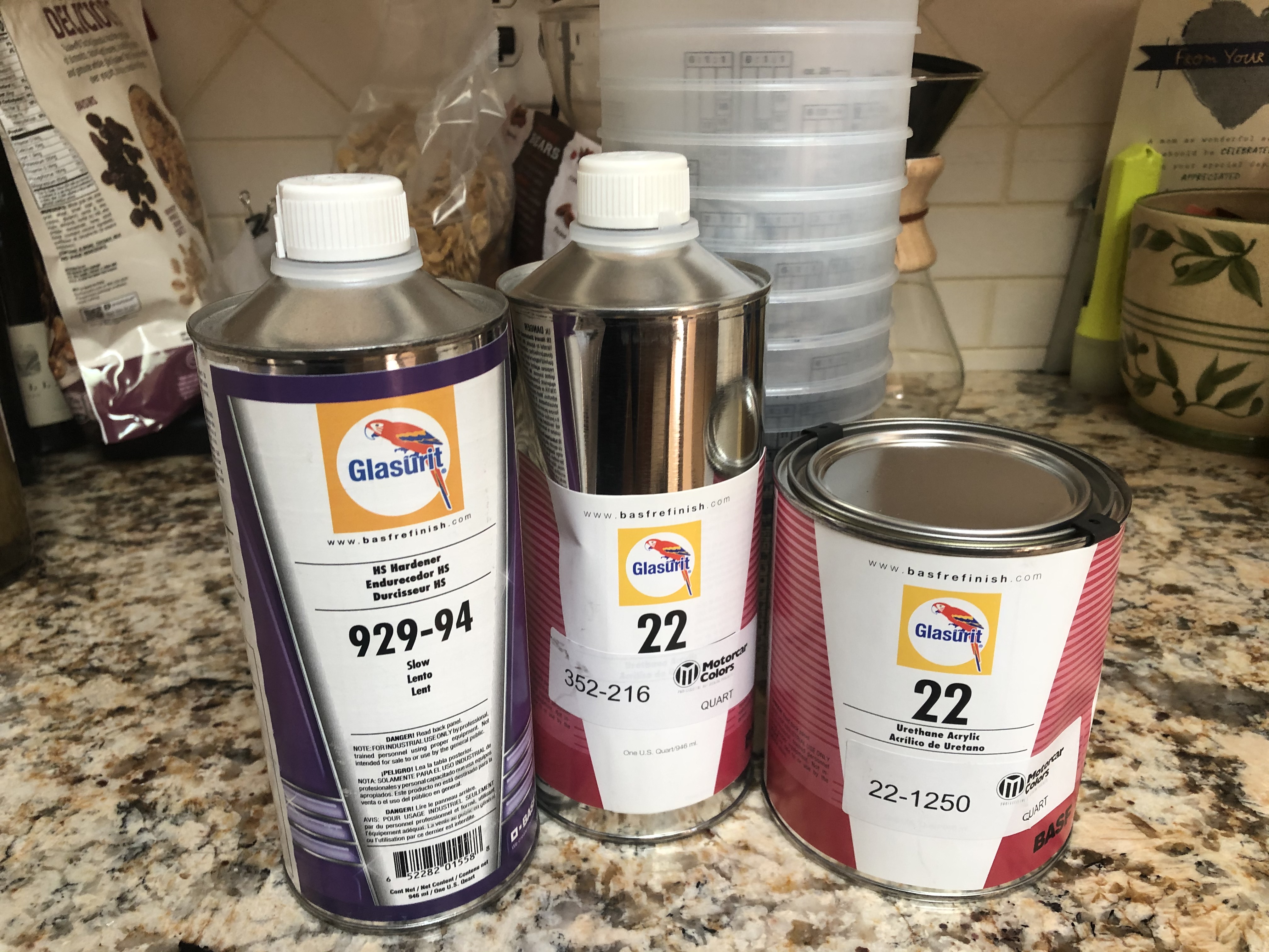
The paint arrived yesterday. Actual honest-to-god single stage Glasurit 22 Line paint. Very excited to have the new paint be so close to the original.
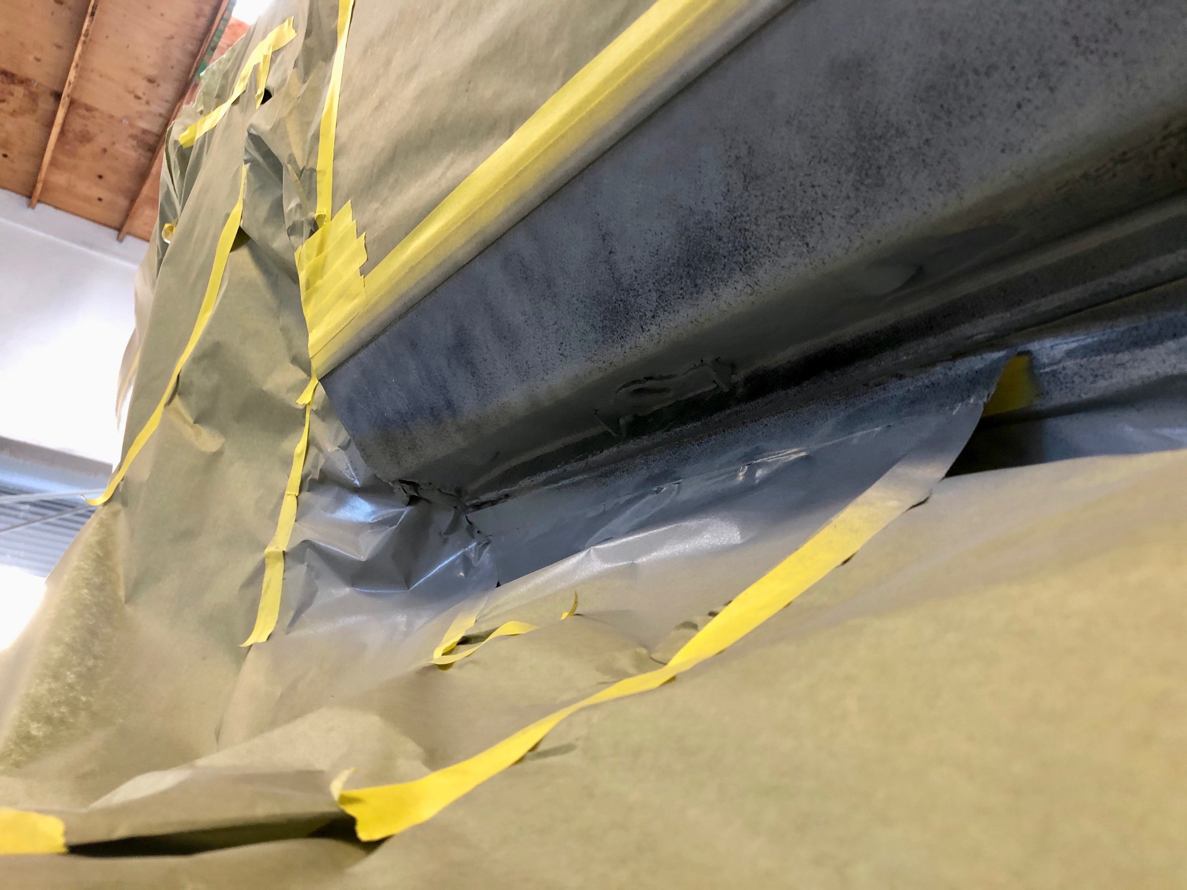
Drove by the shop to drop the paint off, and got a picture of some more work in progress ... nirvana is a straight rocker.
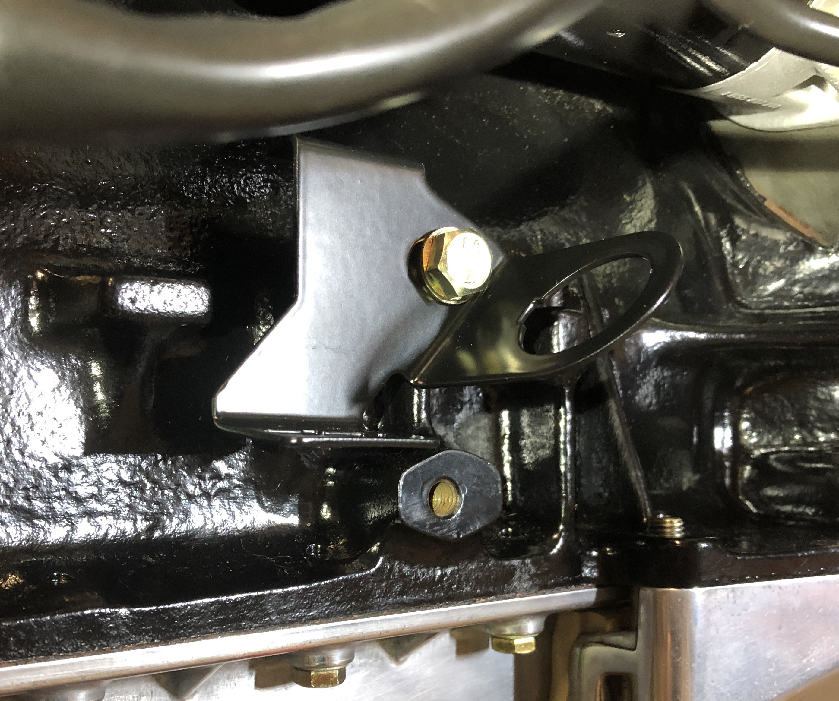
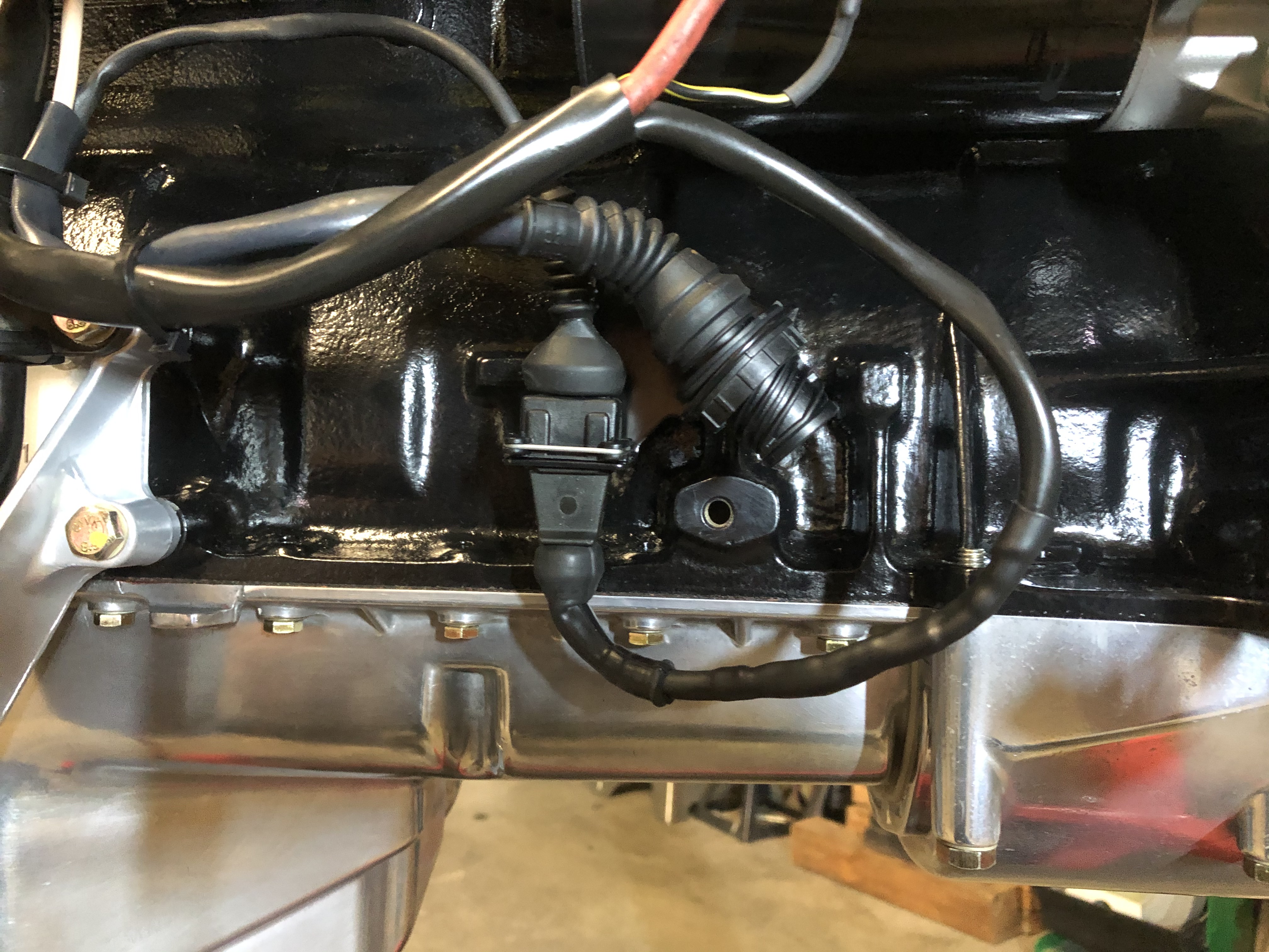
And one edit to the posts above. I hate my crappy potato pic above of the work I did hooking up the 4-wire O2. The M30-B35 O2 sensor wire bracket is pretty cool, but that pic doesn't show it at all, so here's a new and improved potato pic. The bracket was powdercoated in the last batch.

Drove by the shop to drop the paint off, and got a picture of some more work in progress ... nirvana is a straight rocker.

And one edit to the posts above. I hate my crappy potato pic above of the work I did hooking up the 4-wire O2. The M30-B35 O2 sensor wire bracket is pretty cool, but that pic doesn't show it at all, so here's a new and improved potato pic. The bracket was powdercoated in the last batch.


