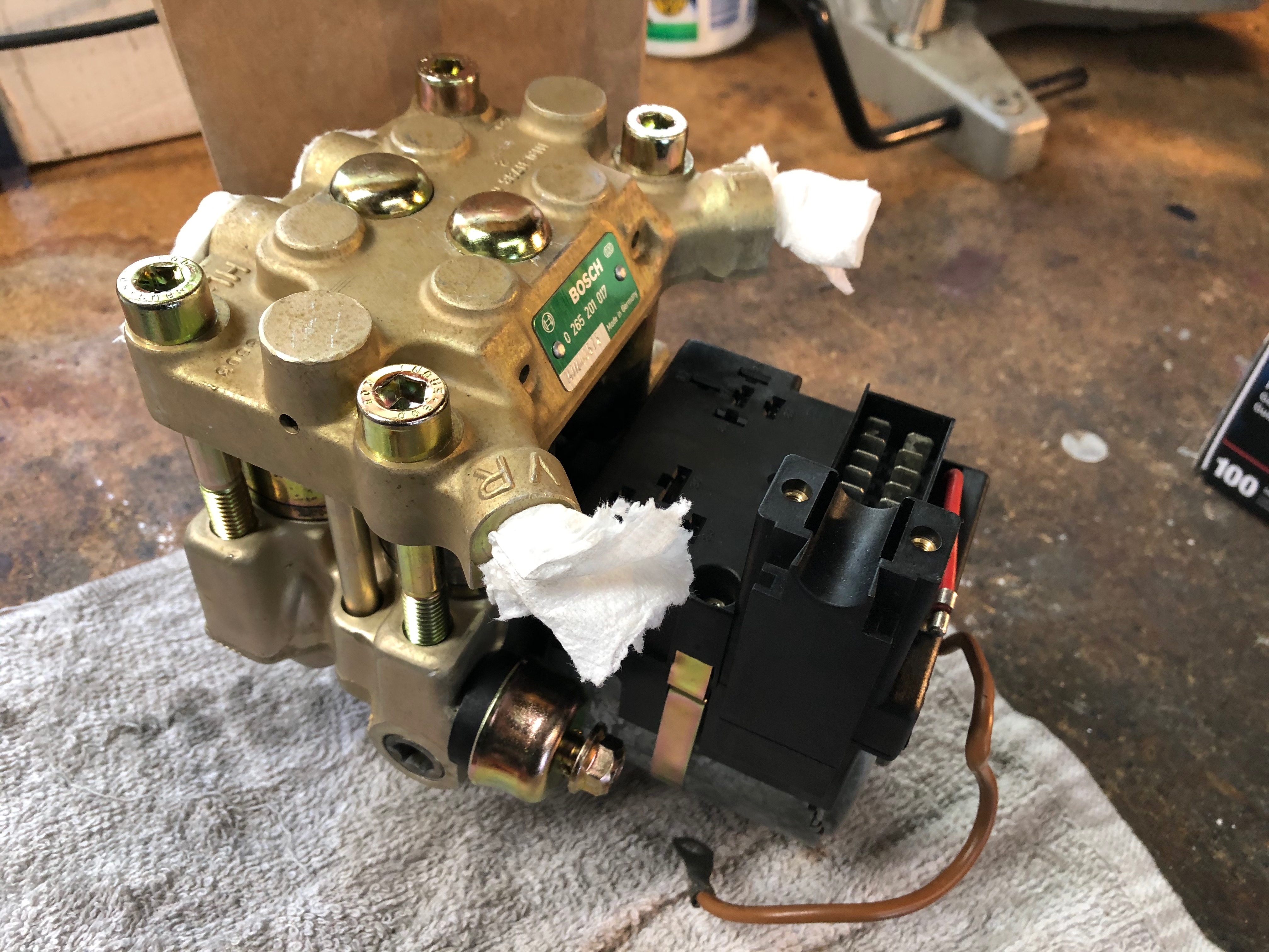
gjargeris wrote:Are replacement parts available for this ABS Hydro Unit. Does anybody know what the technical difference is between a 1988 E28 ABS Hydro Unit Bosch 0265201013 and 026502017? It appear that the former applies to all Series-5, while the latter is for the M5. Are any or all of the parts interchangeable? Thanks.
Unknown about replacement parts but I highly doubt it. Bosch didn't want you to mess with these things and given the sensitive nature and exact demands of an ABS unit, they likely didn't even want regular mechanics mucking about inside them either (hence the security tamperproof Torx bit case screws).
Don't know about the interchangeability either, but they might be since the basic systems are the same. It might be a brake line placement and inlet location or mounting that is different

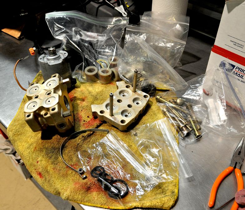
On that note, I tackled this this past weekend. I posted this part in my M535i Restoration thread, but here is the part that is relative to this procedure. This contains some overlap from the previous submissions, so just bear with it. It deals with disassembly only, reassembly is later hopefully after it all has been re-plated:
First off, I wouldn’t have thought this possible if I had not come across this thread:
http://www.mye28.com/viewtopic.php?f=3& ... h#p1339558
Most of what I detail here expands from his thread, but I have filled in some detail where it was missing or a tad vague. So read his thread as background preparation.
The ABS Pump is a relatively simple mechanism really as there aren’t too many moving parts; it’s more like an electronically controlled switch or valve.
Step 1: Disassembly
First, disconnect the brake lines from the pump; use an 11mm Flare End wrench. Unscrew the small center screw that secures the black plastic cover over the electrical connections (it doesn’t come out, it just loosens and stays in the cover). Lift off the cover, set aside and then disconnect the electrical harness plug from the switch. Also remove the two relays.
Next loosen the two bolts on the sides of the ABS that secure it to the fender well through the two dome covered rubber bushings. These bushings are just slip-fitted to two hex shaped studs on the ABS. You kind of need to rock and tilt the ABS towards the back (front end up). Be sure to plug the brake line inlet ports and cover the brake line ends themselves; both will be full of residual brake fluid and WILL leak everywhere.
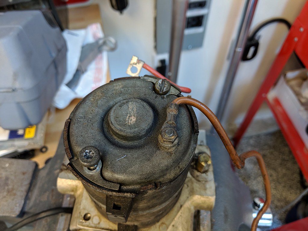
With the ABS on a bench (on top of a towel preferably), you need to remove the electronic module that is piggy-backed on the actual pump unit (the big silver round barrel off the back of the assembly). First disconnect the red power wire, save the really small little screw and washer. Next remove the equally small Torx bit screw over to the side of the top of the plastic terminal:
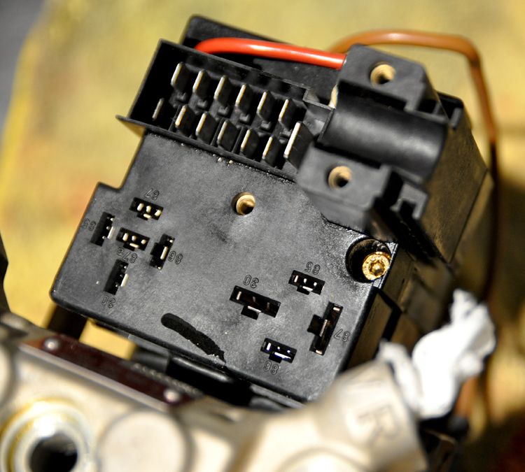
Completely back this screw out, it secures the thin metal band clamp that goes around the barrel of the pump. Once you remove the screw you can pop the band off. Feed the red power wire through the slot on the back of the terminal, then lift the whole terminal off the barrel:
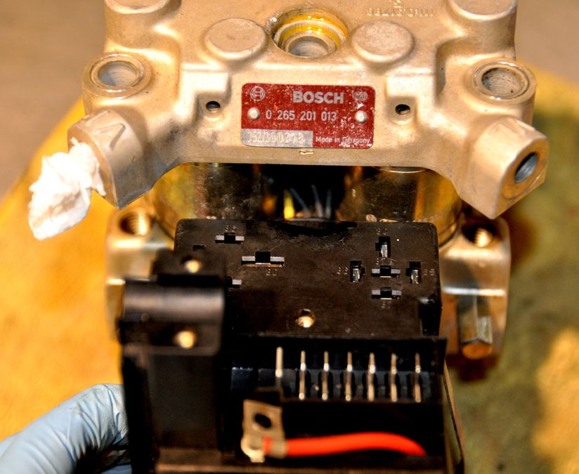
Now you can set about separating the ABS pump into its’ smaller assemblies. First off you need one of these: a 45ITV socket bit, otherwise known as a 5-point Tamperproof Torx Bit:
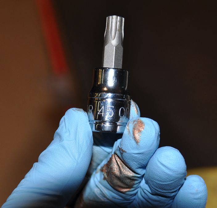
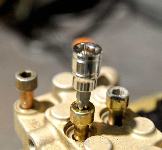
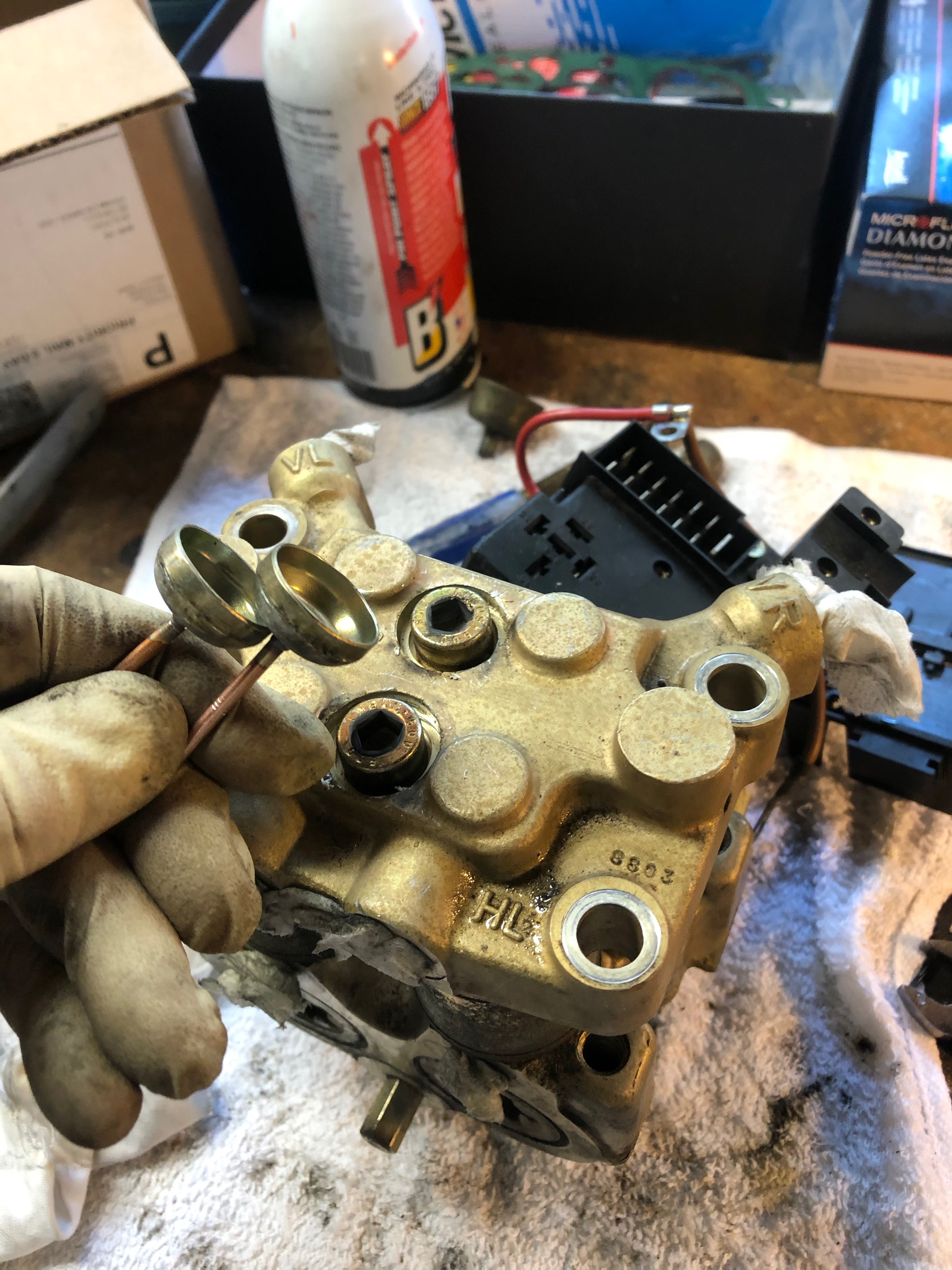
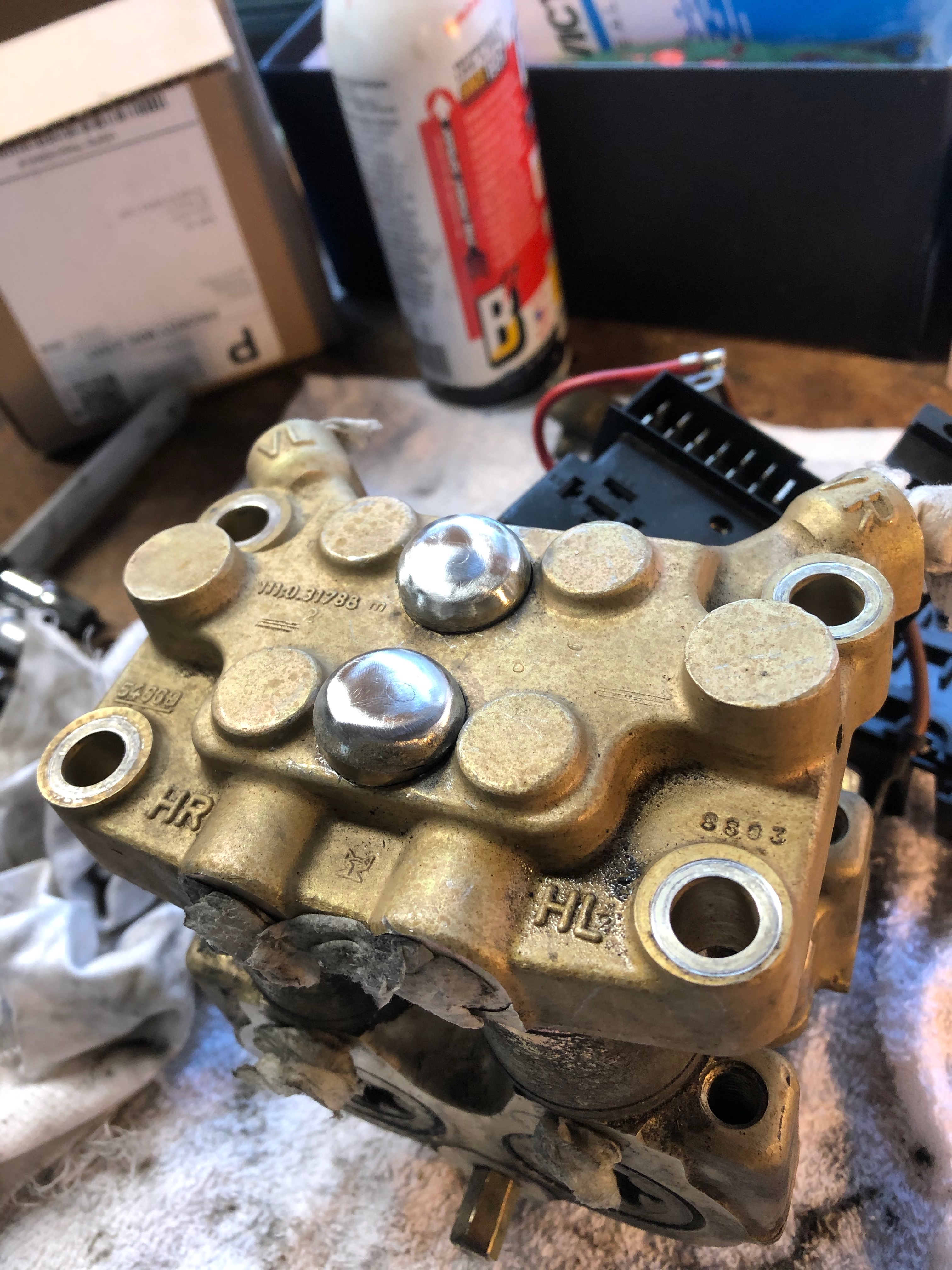
It’s the only way to get the case bolts out (that and a healthy portion of PB Blaster). You need to remove the two domed-shaped cover caps over the two center bolts. Carefully pry them up with a small bit screwdriver, but expect some marring and/or damage; there is no simple easy way to get them off.
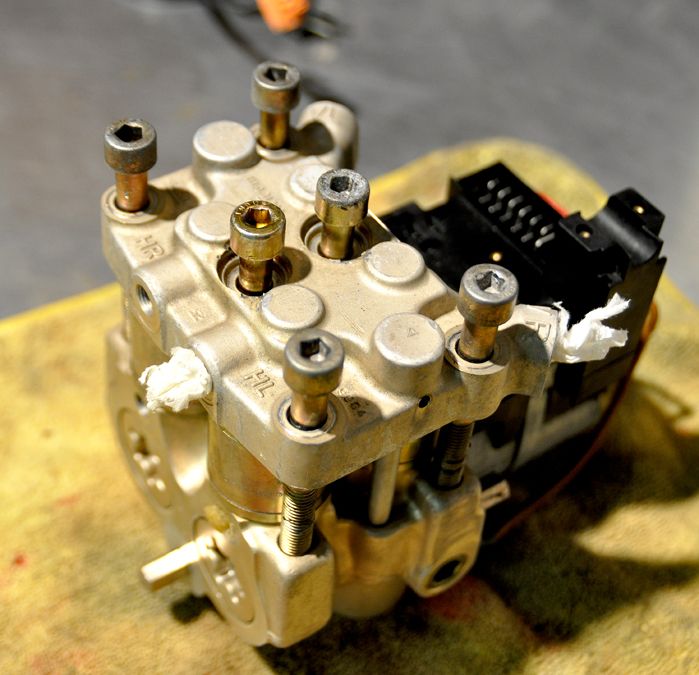
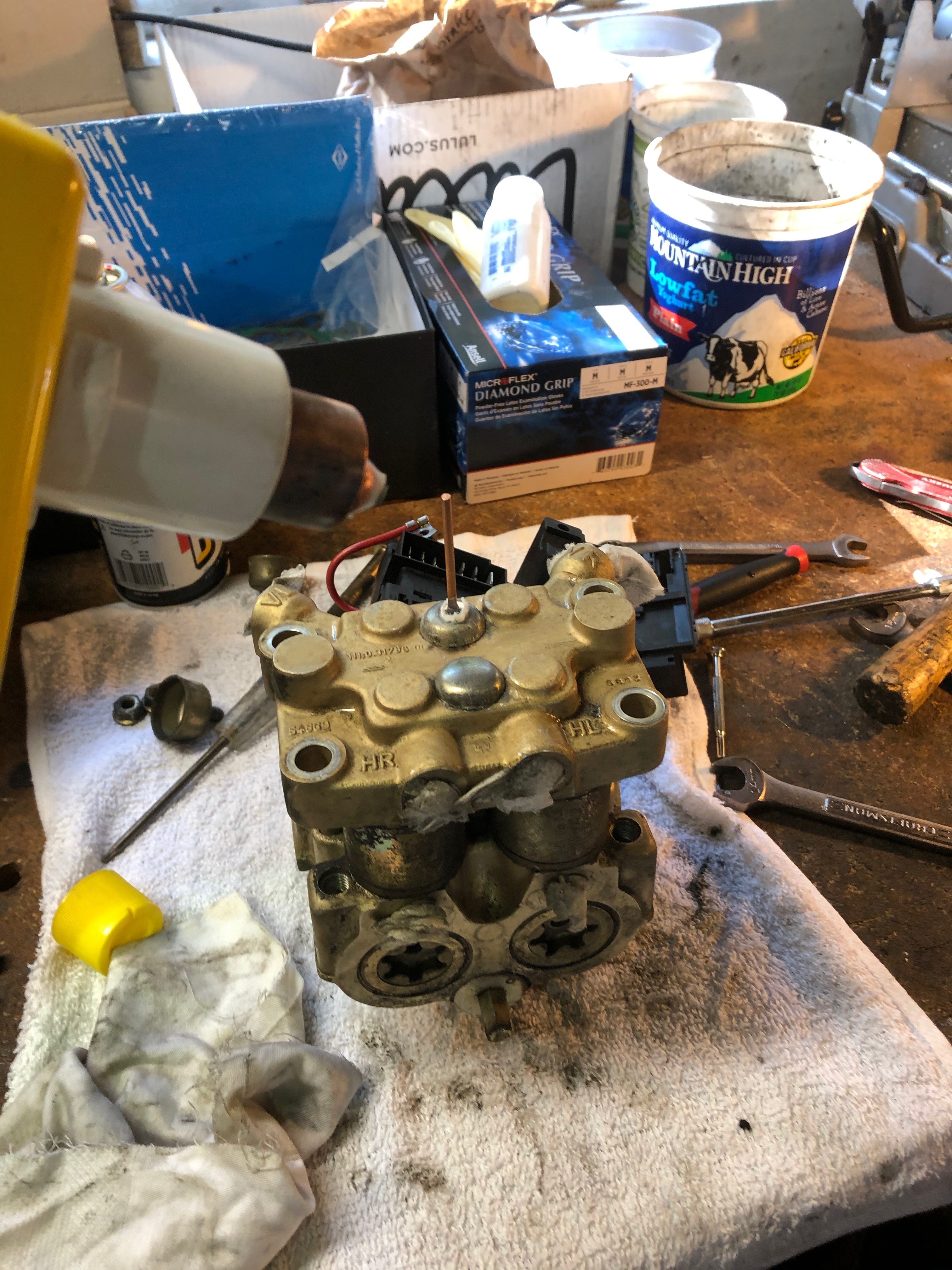
Once the bolts are out, pull the top half up off the base (some gentle prying necessary):
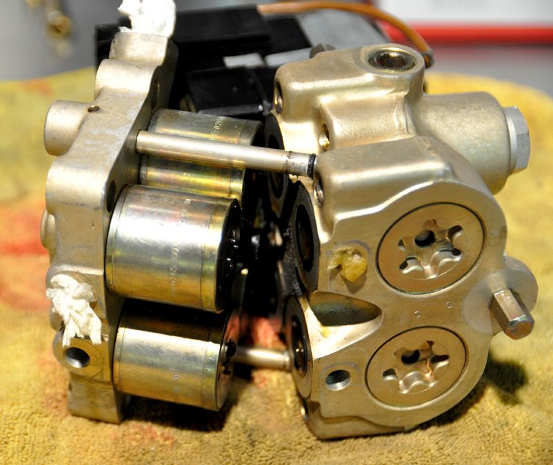
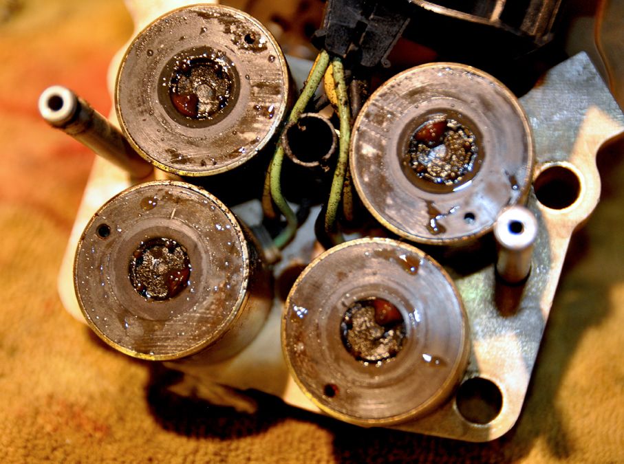
Carefully separate these, the four cylinder filter modules are still hard-wired to the electronic terminal and are only sandwiched between the upper case and lower module. The cylinders will likely be stuck to the upper case cover so you can flip it over. Now you can start to see what the internal condition of the ABS is:
The bottom of the cylinders:
Where the cylinders sit into the bottom assembly:
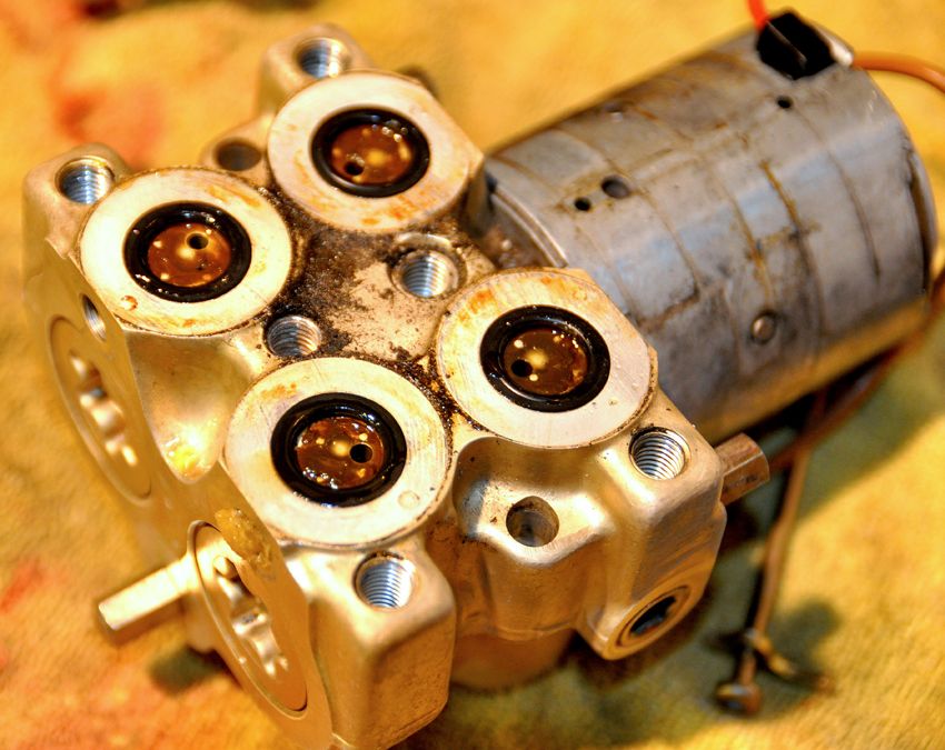
First the bottom section:
There will be four rubber gaskets set in the top of the bottom portion which is notched to receive the cylinders. Carefully pry these out and drop in some de-greaser to clean. You can see from the photo above, this unit has a lot of old gelatin-ized brake fluid pooled up in these wells. A though going over with brake cleaner will clear this up. Be sure to run cleaner through the holes in the bottom of the wells. These connect to the inlet ports on the side of the case (where the brake lines screw into the ABS). It should resemble this when cleaned:
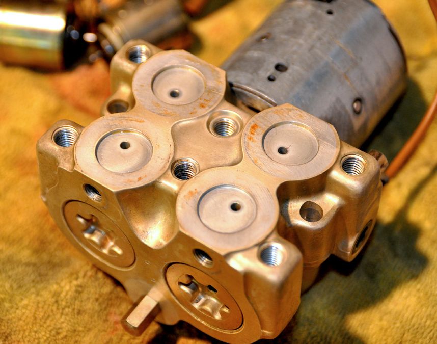
Next, remove the two small hex bit screws on the back of the big cylinder pump. They each have a small, arched plated washer. These are quite long and go all the way through the pump and attach into the top of the back of the lower module:
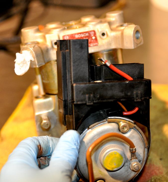
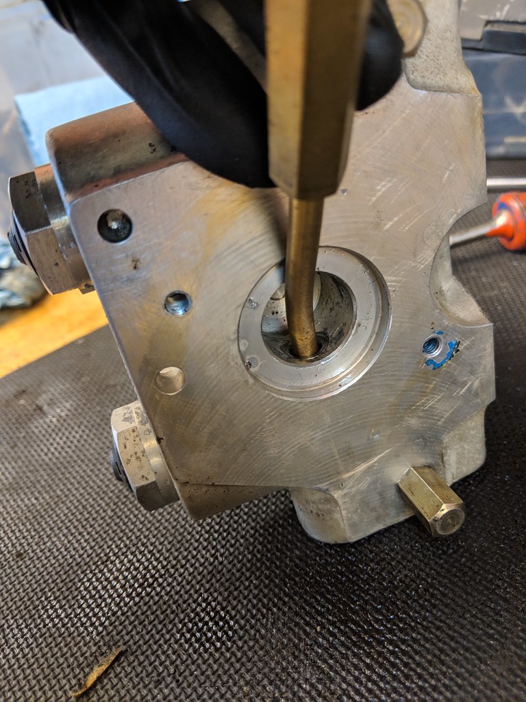
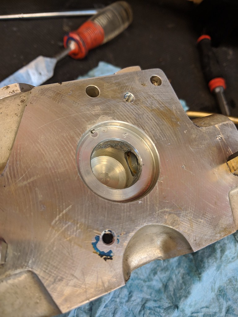
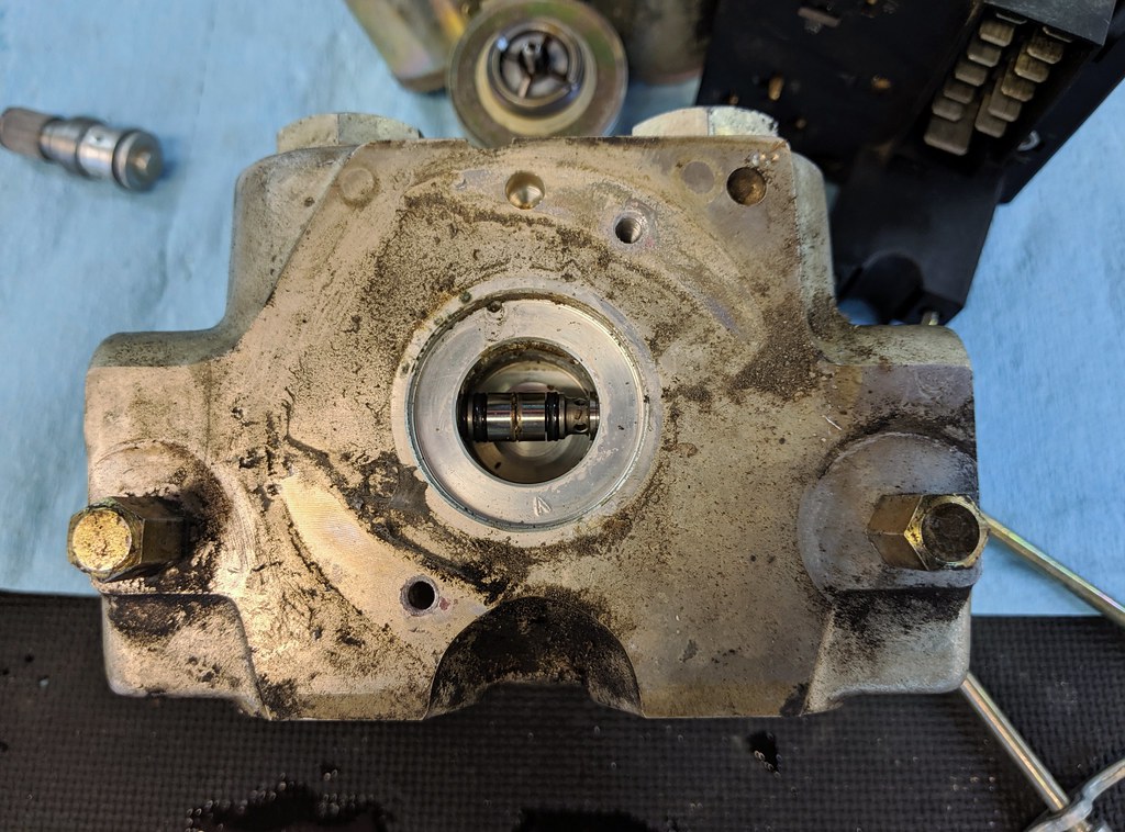
This completely frees the main cylinder pump from the lower half of the ABS module. There is shaft that is fitted into the module, carefully pull these apart and remove the rubber ring gasket that goes around the base of the spindle shaft; set aside and clean thoroughly:
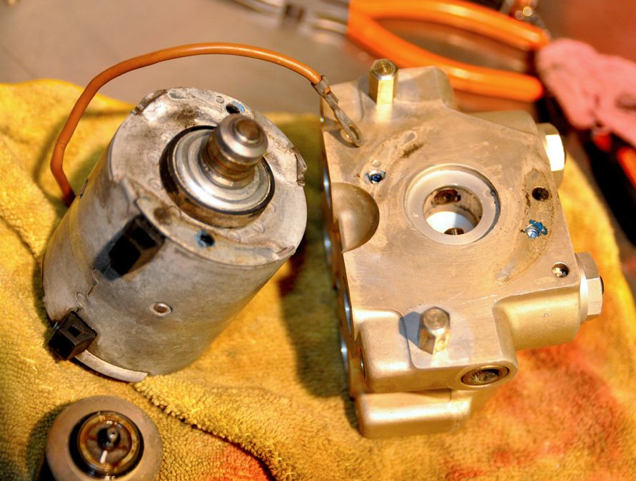
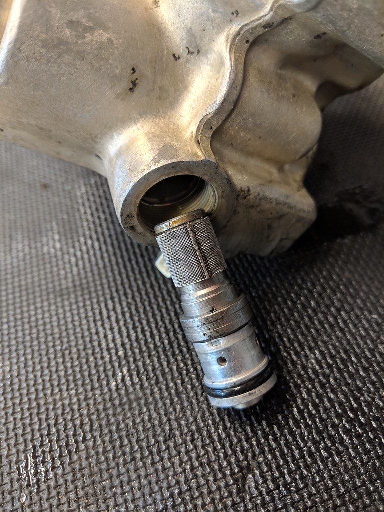
I say carefully because there is a spring loaded cylinder valve of sorts that sits inside a hole in the side of the opening that receives the shaft:
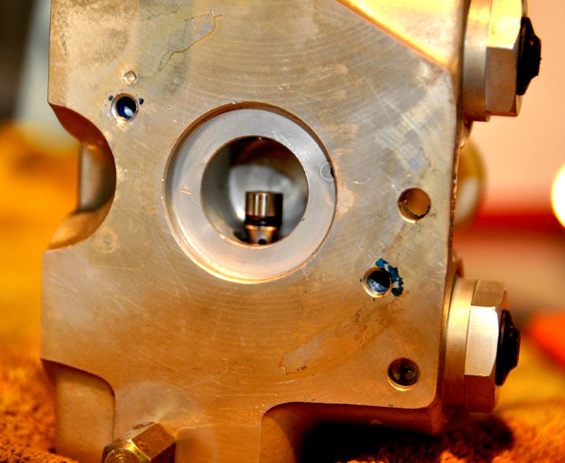
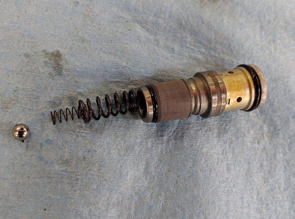
This is actually two springs: a smaller thinner one that rests against an equally small ball bearing both of which sit inside a larger, thicker spring. The small valve is sitting of all these under a fair amount of tension. Be aware there is a very small washer ring that sits on the bottom of this valve between it and the spring, don’t lose it. It’s also a bit tricky to put it all back together, so exercise patience. I wasn’t aware of how tricky it was to reassemble because the old brake fluid gunked it all up so it stuck together until I took the valve out and cleaned everything. Thoroughly clean everything prior to reassembly with brake cleaner including the spindle shaft of the cylinder pump that fits into the lower module; it should spin freely. You can chose to reassemble right away following a reverse procedure. I haven’t quite figured out how to insert the spindle shaft back into the lower module yet (you have to find a way to depress the valve in order to fully insert the shaft). I was going to employ a bent piece of thin metal shim (bent at 90 degrees) to apply pressure to depress the valve, then slip the spindle in and slide the shim out. (This is the method used to rebuild and clean Craftsman socket wrenches when dealing with a similar assembly for the ratcheting assembly, but I digress).
However, I am repainting/refinishing the pump barrel as it is aged aluminum and looking a bit tired. I am going through all this effort to beautify the engine bay so why cut corners now?
Second the top section:
As mentioned the four smaller cylinders are just pressure fit into the top case cover; aged fluid is the only thing holding it all together. Give them a small tap and they will pop off:
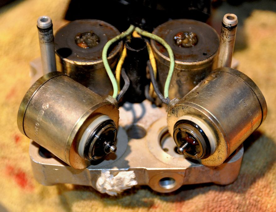 NOTE:
NOTE: Make yourself a diagram noting which cylinder goes where relating to the case cover; it is important. There are no designations on the cylinders themselves. You can use the wire colors as an aid (black/green vs. black/yellow). Find some way to mark the cylinders themselves, preferably one that doesn’t rub off (hint, Sharpie wasn’t it).
Once this happens, set the whole terminal and cylinder assembly aside and deal with cleaning the upper case cover:
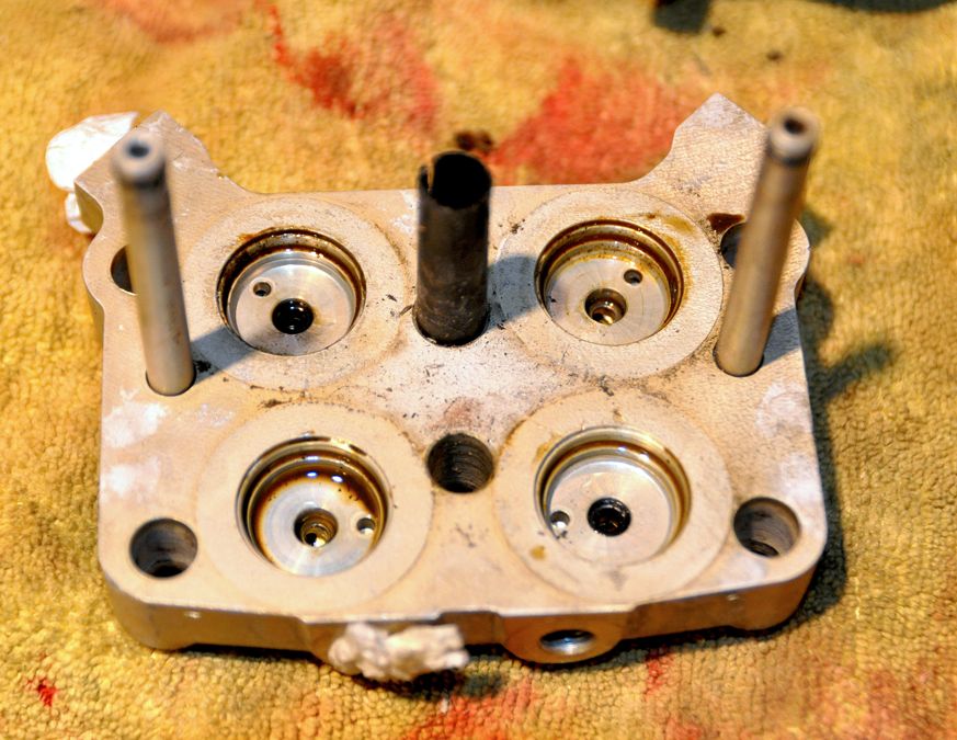
Again, run brake cleaner through it completely cleaning out all the holes and ports. There is hollow black plastic tube acting as a sort of sleeve for one of the case bolts. Pull it out for cleaning, be sure to remember the orientation.
With that done you can turn you attention to the cylinders themselves. Each cylinder is a small sub-assembly unto themselves:
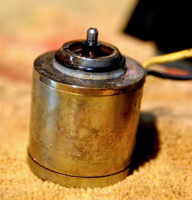
First remove the two washer rings on the top, one white plastic and one black neoprene. Clean and set aside:
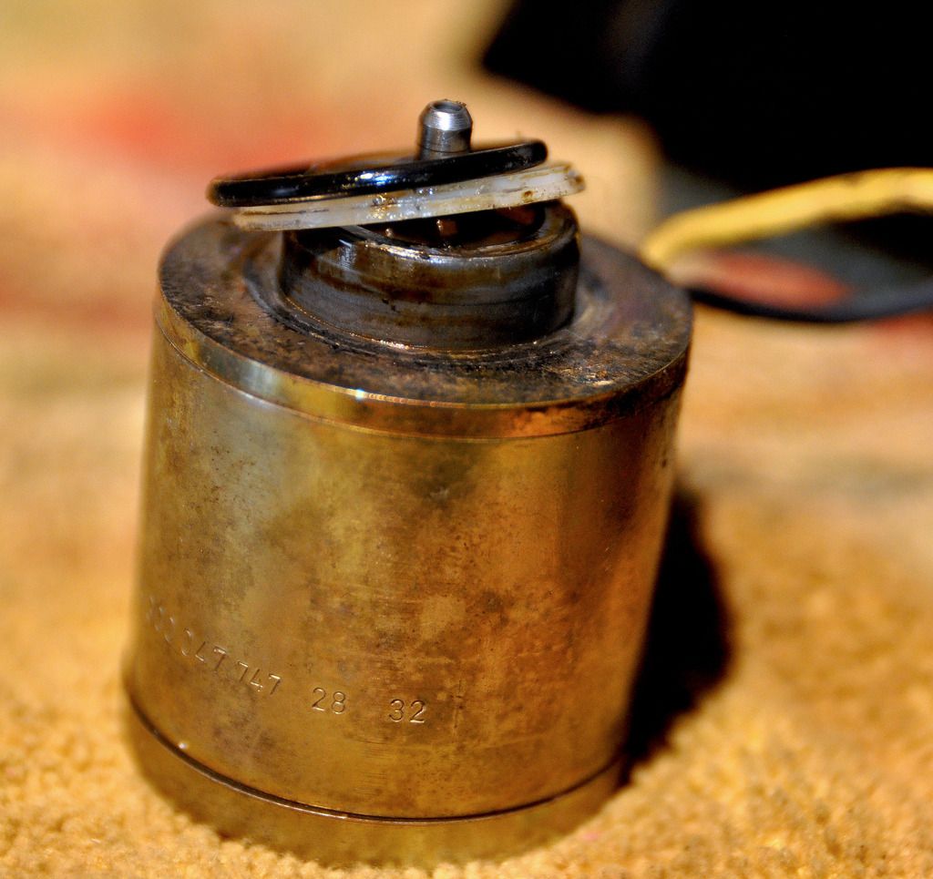
Next there is Cad plated ring which covers the inner coil. Carefully pry it off, it will be stuck on:
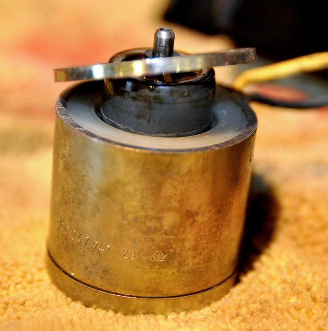
Then slip the center shaft out the bottom, separating it from the inner coil. Put the center shaft aside, we’ll get to it in a minute:
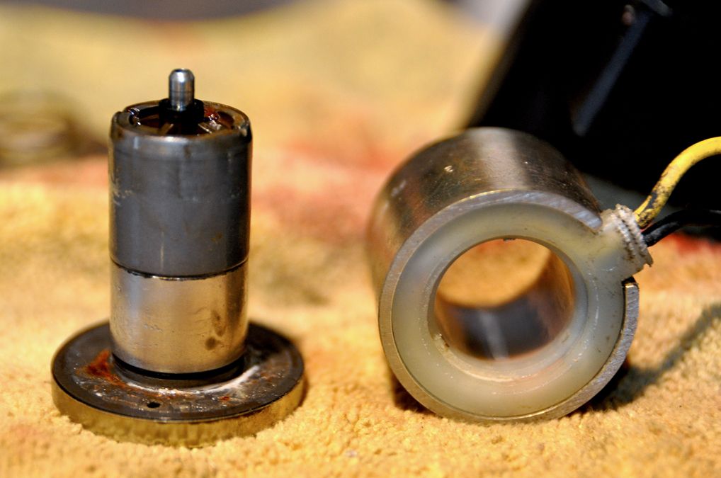
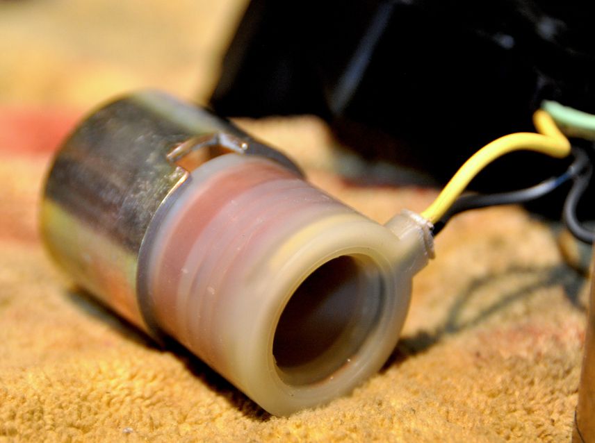
Pull the inner coil out from the Cad plated cylinder case. Thoroughly clean each item (this is where I made my markings identifying each cylinder: Inside of the plated case and on the outside of the inner coil):
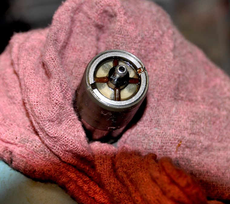
Now turn you attention back to the center shaft. You may not be able to tell, but at each end of this shaft there is an extremely fine micro screen filter that the brake fluid is pushed through. It will likely be gunked up pretty heavy with old fluid so don’t go at it with anything other than a blast of brake cleaner. Thoroughly clean the rest of the shaft:
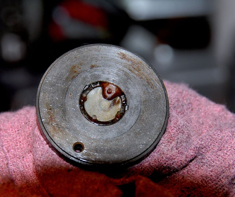
The last item to remove and clean is a thin Cad plated ring that slips around the large base of the shaft:
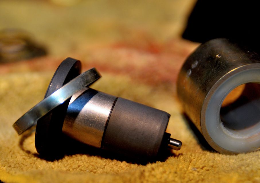
Needless to say, bag & tag and photo everything. I’m taking all the Cad plated stuff over to the plater this week to see if they can re-plate the ABS module case itself (carefully covering the delicate parts and Bosch ID tag, of course).
