ABS unit cleaning procedure
-
harrypalmer
- Posts: 670
- Joined: Jul 25, 2012 12:10 AM
- Location: Denver, Colorado
Re: ABS unit cleaning procedure
Really great pictures with mostly step by step detailed explanation. Very inspiring and useful. Thank you!
After having had my E28 Brake Master Cylinder replaced with a new one from an E32, plus a new Brake Bomb, now I have a MASSIVE Brake Fluid AND Power Steering fluid leak coming down the Brake Booster. So with your decisively great post I am feeling more and more inspired to tackle the above and disassemble the ABS unit once and for all, as I've never had ABS function aside from the amber indicator light ON. Thank you once more.
After having had my E28 Brake Master Cylinder replaced with a new one from an E32, plus a new Brake Bomb, now I have a MASSIVE Brake Fluid AND Power Steering fluid leak coming down the Brake Booster. So with your decisively great post I am feeling more and more inspired to tackle the above and disassemble the ABS unit once and for all, as I've never had ABS function aside from the amber indicator light ON. Thank you once more.
Re: ABS unit cleaning procedure
I wonder how much of this cleaning could be accomplished if you removed the ABS module and flushed a bunch of brake cleaner through the inlets and outlets. Any thoughts? Seems it would be much easier, particularly for a unit that isn't leaking.
Re: ABS unit cleaning procedure
ok I am in the same situation, no brake fluid coming out of my front driver's side caliper after big brake conversion. But before I embark on taking apart my ABS module, I would like to activate solenoid and brake pump, just to see if I can flush it that way..
any idea how to jump relay for solenoid and pump.
any idea how to jump relay for solenoid and pump.
Re: ABS unit cleaning procedure
Refer to this topic http://www.mye28.com/viewtopic.php?t=119383 for ABS connector pin outs.
To activate pump, turn ignition to RUN and ground 28.
To activate solenoid valve, turn ignition to RUN, ground 27 and also ground 2 (FL), 18 (RL), 19 (RR) or 35 (FR) as required.
Do both at once to get the fluid flowing.
Pins 10 and 20 are grounds.
To activate pump, turn ignition to RUN and ground 28.
To activate solenoid valve, turn ignition to RUN, ground 27 and also ground 2 (FL), 18 (RL), 19 (RR) or 35 (FR) as required.
Do both at once to get the fluid flowing.
Pins 10 and 20 are grounds.
Re: ABS unit cleaning procedure
great man thank you, that is what I was looking forJohnH wrote:Refer to this topic http://www.mye28.com/viewtopic.php?t=119383 for ABS connector pin outs.
To activate pump, turn ignition to RUN and ground 28.
To activate solenoid valve, turn ignition to RUN, ground 27 and also ground 2 (FL), 18 (RL), 19 (RR) or 35 (FR) as required.
Do both at once to get the fluid flowing.
Pins 10 and 20 are grounds.
Re: ABS unit cleaning procedure
I'm doing this now. I learned some things I didn't see above that I figure would make this awesome thread even more awesome.
Vince noted above he hadn't re-assembled the pump when he posted the above. He said he hadn't figured out to get the motor re-installed, given the spring based thingies would need to be pushed out of the way. I figured this out.
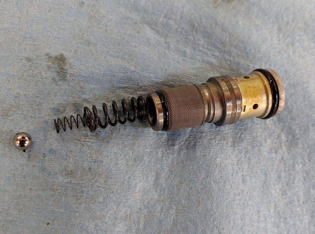
After removing the pistons (be very careful as there are TWO springs and ball bearing behind each). Just press them both to one side; the near side will come out. Then do the other.
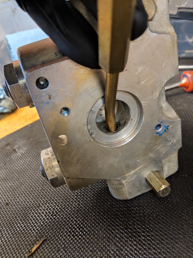
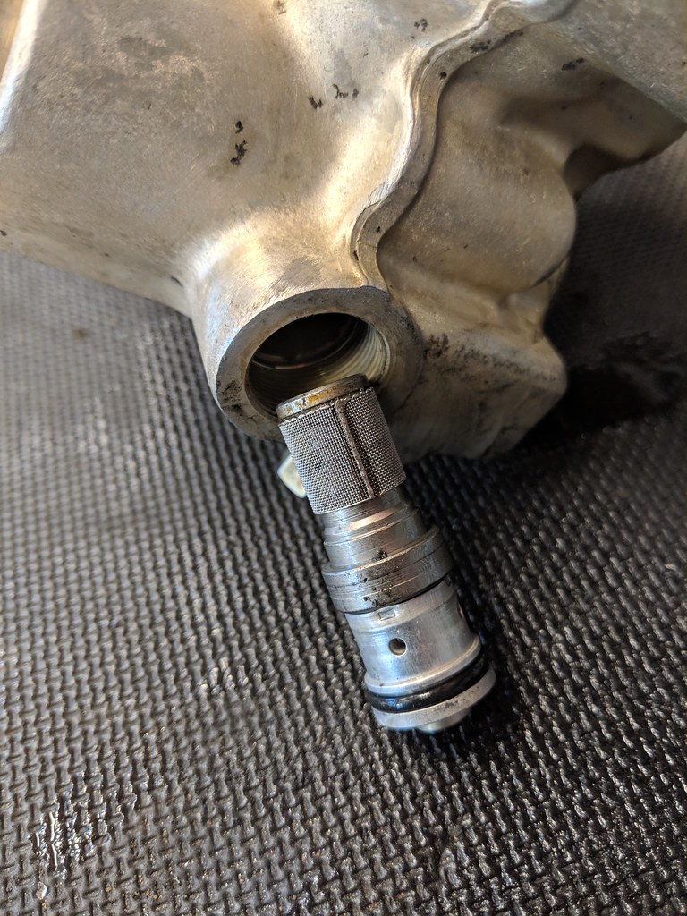
The trick I figured out today is how you'd re-assemble things: You have to remove the sleeves (plus filter assemblies) that these two pistons go into. First remove the two screw caps (hex bolt) on each side and then use a brass drift (mine is perfectly bent which helps) to tap the piston sleeves out:
I'll now clean all this out:
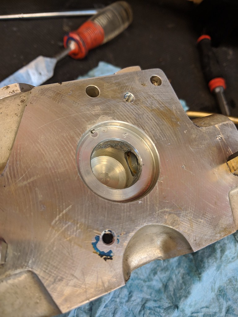
I was puzzled how all this worked. The spindle on the motor looks perfectly round and there's no obvious way for the motor's rotation to cause a mechanical energy transfer into the pump. What I noticed is the spindle on the motor is NOT round. Oblong by about 1mm. As it rotates it alternately presses the pistons in. It's pretty clear looking at the pistons and sleeves how the fluid dynamics (well it was to me once I noticed the oblong nature of the spindle).
Vince noted above he hadn't re-assembled the pump when he posted the above. He said he hadn't figured out to get the motor re-installed, given the spring based thingies would need to be pushed out of the way. I figured this out.
After removing the pistons (be very careful as there are TWO springs and ball bearing behind each). Just press them both to one side; the near side will come out. Then do the other.
The trick I figured out today is how you'd re-assemble things: You have to remove the sleeves (plus filter assemblies) that these two pistons go into. First remove the two screw caps (hex bolt) on each side and then use a brass drift (mine is perfectly bent which helps) to tap the piston sleeves out:


I'll now clean all this out:

I was puzzled how all this worked. The spindle on the motor looks perfectly round and there's no obvious way for the motor's rotation to cause a mechanical energy transfer into the pump. What I noticed is the spindle on the motor is NOT round. Oblong by about 1mm. As it rotates it alternately presses the pistons in. It's pretty clear looking at the pistons and sleeves how the fluid dynamics (well it was to me once I noticed the oblong nature of the spindle).
Re: ABS unit cleaning procedure
^^^Great follow-up, Charlie.
I had no idea there was a whole sleeve assembly that the spring-ed piston sat in. Wish I had so that I could have cleaned them out completely.
The Power Steering Pump works similar in terms of having an oblong/non-symetrical spindle.
I had no idea there was a whole sleeve assembly that the spring-ed piston sat in. Wish I had so that I could have cleaned them out completely.
The Power Steering Pump works similar in terms of having an oblong/non-symetrical spindle.
-
ScottKendall
- Posts: 67
- Joined: Jul 07, 2015 10:01 PM
- Location: Kentucky
Re: ABS unit cleaning procedure
Glad to see we are all in ABS brake pump hell together. I have some pics to post once I get this thing worked out where there is more sludge in to block. Here is my $64,000 question, what if you have a 15 pin diagnostic port?
If no one answers, I'll probably have to make a rig for the plug into the pump.
If no one answers, I'll probably have to make a rig for the plug into the pump.
Re: ABS unit cleaning procedure
I might have misunderstood your question, but as far as I know, the Diagnostic Connector and its wiring (on the inlet manifold) has absolutely nothing to do with the ABS system.
What are you trying to do?
What are you trying to do?
Re: ABS unit cleaning procedure
Damn. That second picture looks like a smaller version of a modern BMW VANOS actuator. 
Re: ABS unit cleaning procedure
More pr0n that I wished I had available before taking this job on. These details should help others with the pump pistons...
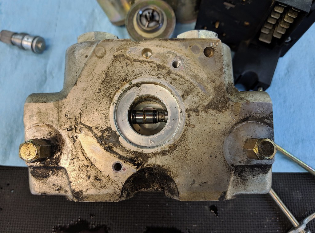
When you remove the pump motor, be VERY careful with the two screws that hold it in place. They used a heavy amount of locktite and the torx heads are easy to strip. This was nerve wracking...
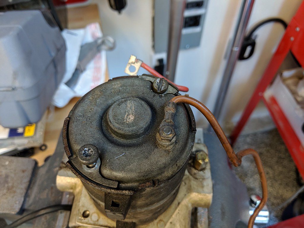


When you remove the pump motor, be VERY careful with the two screws that hold it in place. They used a heavy amount of locktite and the torx heads are easy to strip. This was nerve wracking...

Re: ABS unit cleaning procedure
My alternate method of removing those caps ... use a stud welder, pull the caps straight up, then cut-grind-buff:
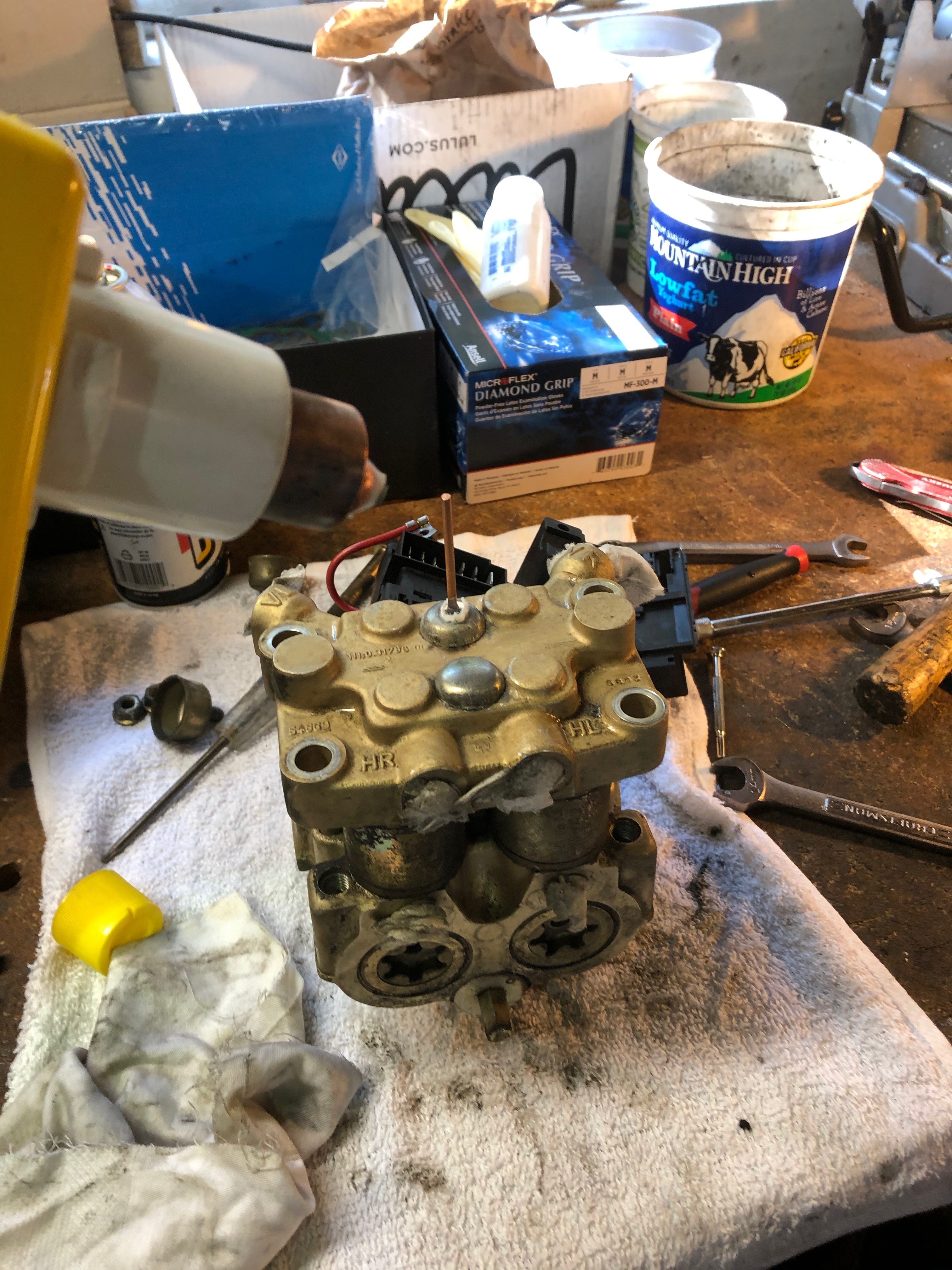
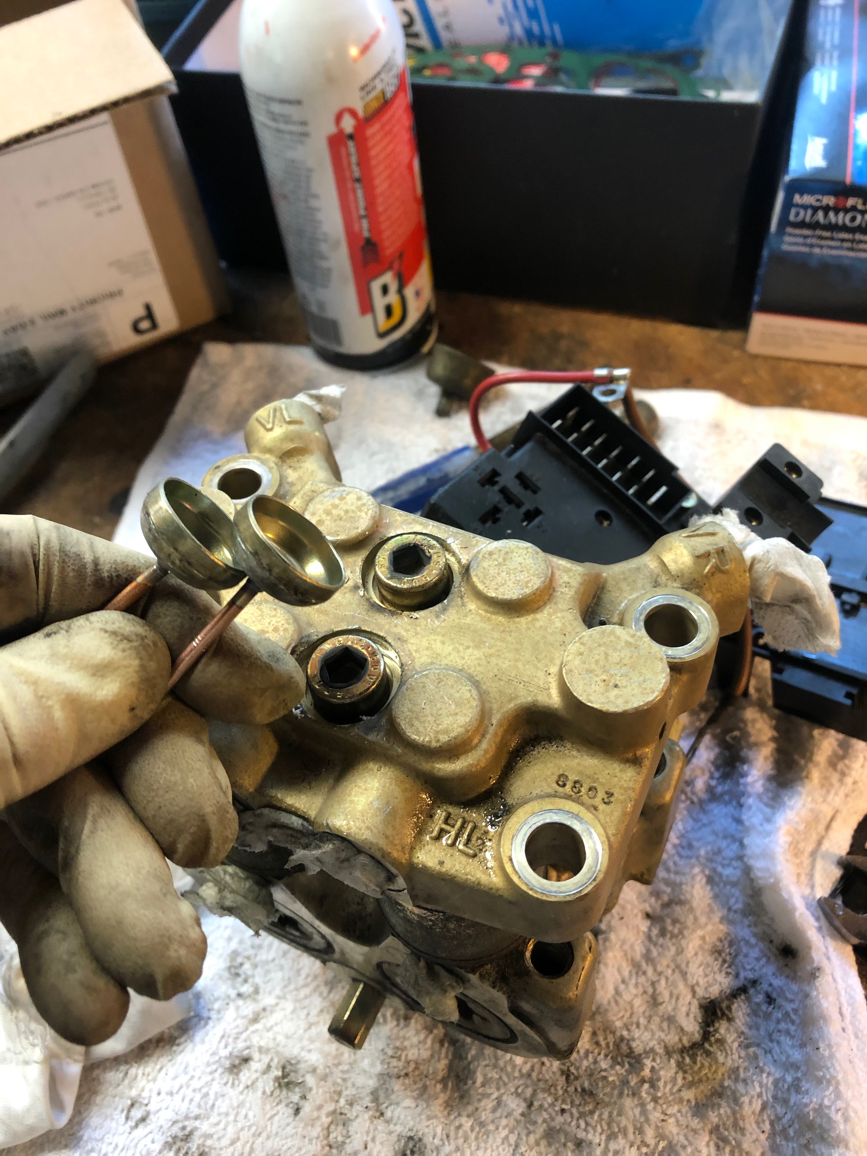
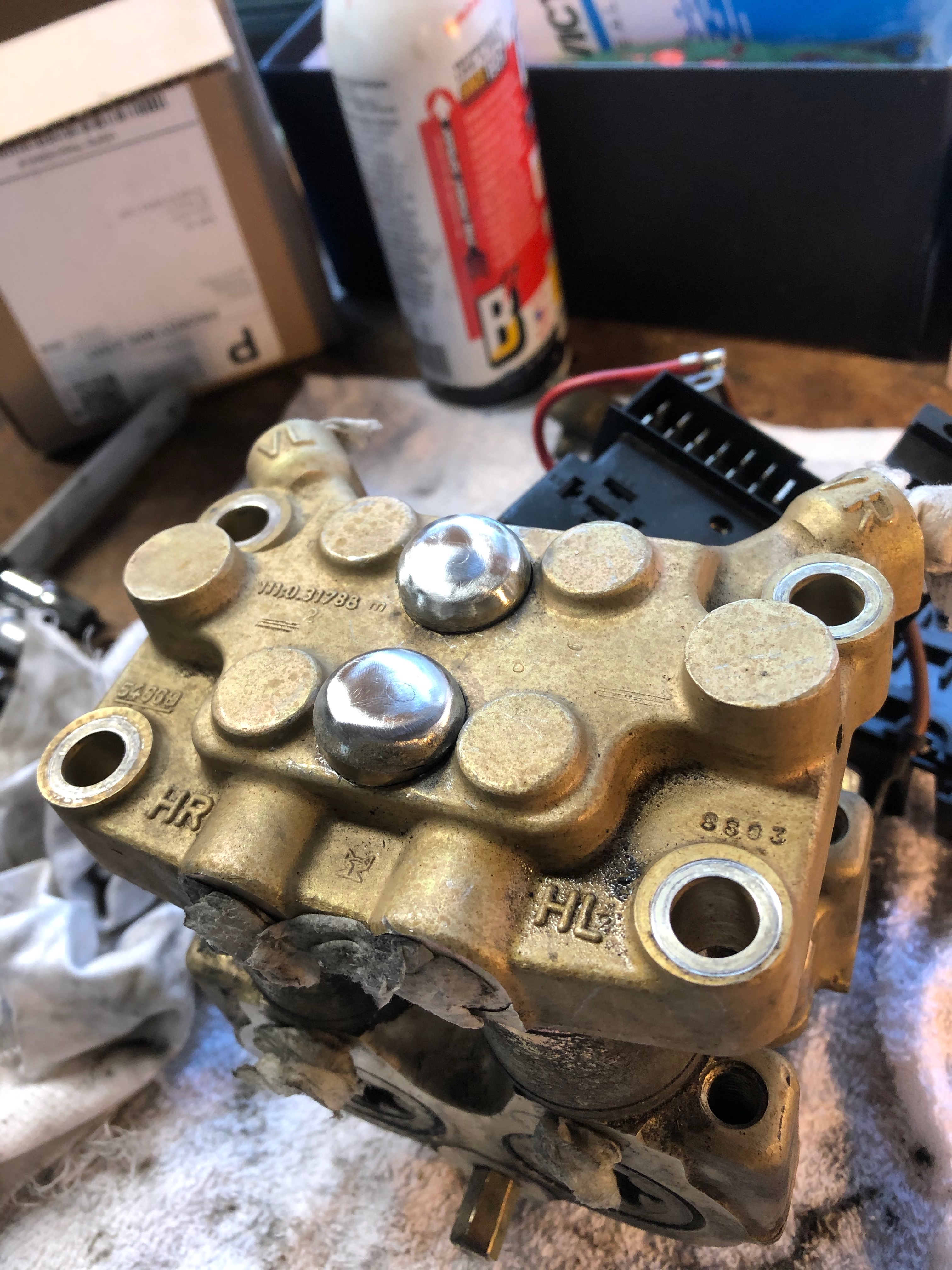
If I'd thought of doing this before I tried to pry them out, the aluminum cap on the pump wouldn't have been marred at all. The caps went off to plating, and here's what they looked like after reassembly:
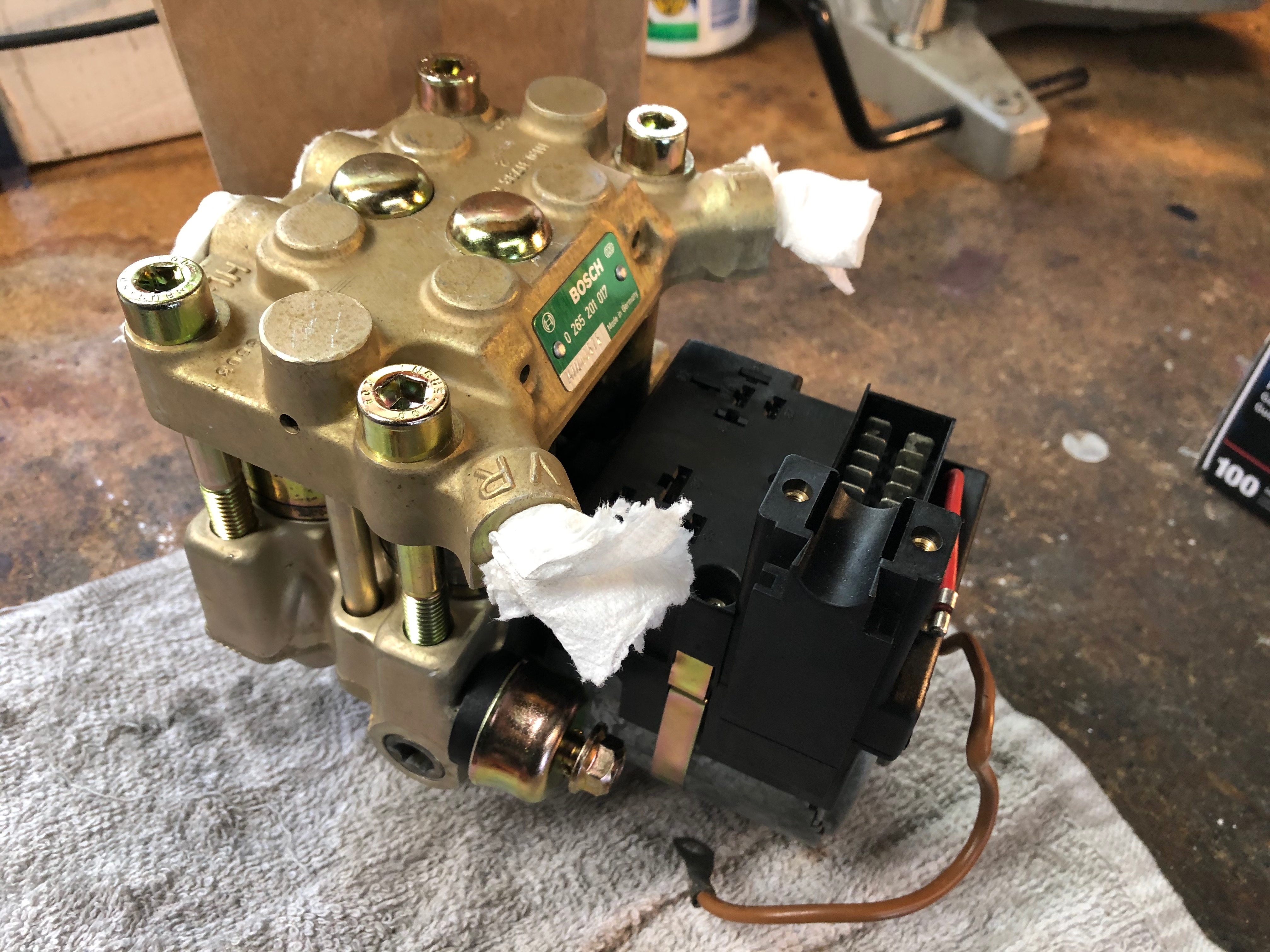
Also, once I got the studs welded on, the caps came out really, really easily. That makes me think that a stud welder is maybe overkill, and that a wooden dowel and a really good, high-temp glue gun would have worked as well. And if you did that, you might not even have to get the caps replated.
Last addition: I didn't see torque specs here for those big M10 "penta" bolts. So I reverted to standard ... Standard torque spec for M10 is 50 Nm, with BMW specifying a 30% reduction in torque for plated bolts, so that gives you 35 Nm. I torqued the bolts in two stages ... about 15 Nm first, then all the way up to 35 Nm. Also, I did an "X" pattern for tightening ... outside corners first in an "X" pattern, then the two center bolts.


If I'd thought of doing this before I tried to pry them out, the aluminum cap on the pump wouldn't have been marred at all. The caps went off to plating, and here's what they looked like after reassembly:

Also, once I got the studs welded on, the caps came out really, really easily. That makes me think that a stud welder is maybe overkill, and that a wooden dowel and a really good, high-temp glue gun would have worked as well. And if you did that, you might not even have to get the caps replated.
Last addition: I didn't see torque specs here for those big M10 "penta" bolts. So I reverted to standard ... Standard torque spec for M10 is 50 Nm, with BMW specifying a 30% reduction in torque for plated bolts, so that gives you 35 Nm. I torqued the bolts in two stages ... about 15 Nm first, then all the way up to 35 Nm. Also, I did an "X" pattern for tightening ... outside corners first in an "X" pattern, then the two center bolts.


