

Hi guys, new to the forum, and looking for some tech advise
My central locking system is not working on my '86 535i, it does not work at all from any of the doors locks or from the trunk lock, the car for sure has central locking in it because it has all of the actuators in place....I have also tried swapping the central locking control unit with a known working one and still nothing.....Would anyone have an idea on how I could troubleshoot the system?
thanks in advance
Rene
External links now open in a new browser tab - turn this off in your UCP - Read more here.
Central Locking System
-
LandCruzer94
- Posts: 2043
- Joined: Jan 24, 2009 6:13 PM
- Location: Simi Valley, California
-
Mark 88/M5 Houston
- Posts: 8548
- Joined: Feb 12, 2006 12:00 PM
- Location: Far North Houston
This and a copy of the ETM for your car should get you headed down the path to getting it working again.
E30 / E28 central locking FAQ
Prepared by Christopher A. Pawlowicz (chrisp@doe.carleton.ca)
(If you'd like this emailed to you via within minutes, send a blank email to centrallock@mesaperformance.com)
This FAQ covers central locking on E30 (3 series '84-'91) and E28 (5 series '82-'88) cars. It also seems to apply to E24 (6 series '76-'89) and maybe other.
1.0 Introduction
2.0 Functional Overview
3.0 Common Problems and how to fix them
4.0 4.0 Related Accessories
5.0 Door Lock Repair Kit Instructions
6.0 Central locking troubleshooting guide (by Jim Conforti)
1.0 Introduction
Lock system/ production years/ models:
Central locking was standard, but early models (<'85) do not have the double-lock feature. Starting somewhere in 1985 model year, the double lock feature became standard. Actually, it seems that the double lock feature was used in all E30's with production date 9/84 and up. E28's seemed to start 1/85 or mid year production.
Early models had keys marked with an 'I' and where shorter, using a 4 digit key code. Later models are marked with an 'S' and have longer keys with a 5 digit key code. The double-lock feature is engaged with the last section of the key - the valet key is shorter than the regular keys and does not engage the double lock.
2.0 Functional Overview ( by Paul Reitz prreitz@amp.com BMW CCA #1167)
Intended Operation
The system allows the entire car to be locked from either front door key lock, the trunk key lock, or by depressing the driver's door lock button inside the car. It also allows the car to be double-locked (from the driver's side key lock) so an intruder cannot unlock the car just by breaking a window or using a tool to lift one of the door lock buttons. If the car is locked - but not double-locked - it can be unlocked via the key lock from either front door or the trunk, or by lifting either front door lock button from the inside. The doors automatically unlock via an inertia switch that operates on impact greater than 5g. Door lock buttons on 4 door models have no control over central locking, although they can lock, and under certain circumstances unlock that particular door. Never double-lock a car with occupants inside!
The system consists of the following components: Key lock cylinders in each front door (and the trunk), which operate the door latches that prevent the door handles from operating, and which in turn have mechanical linkages to the door lock button and to the door lock motor unit mounted inside the door cavity. (There is also a trunk lid lock motor unit that locks the trunk latch button, and a gas filler lock motor.) Most door lock motor units have two motors: = the door lock motor, which operates the door latch locking mechanism and door lock button, and the double-lock motor, which "pins" the mechanical linkages and the door latch so they cannot be manually unlocked. The driver's door and trunk lack the double-lock motor; the trunk doesn't need one, since there's no "lock button" there, and the driver's door is double-locked by the mechanical constraint of the 90 degree position of the key lock cylinder. The door lock motor unit also contains the lock and unlock switches which send "lock" and "unlock" signals to the Central Lock Control Unit (CLCU). The CLCU contains some electronics and the LOCK and UNLOCK relays, each of which has a set of normally-open and normally-closed contacts with a common connection, and which operate all door motors. The CLCU is located behind the speaker in the left front kick panel.
In addition, there are microswitches mounted on the front door key lock cylinders. On the driver's door, this is the "unlock inhibit" microswitch, which closes only when the key lock cylinder is rotated to the 90 degree position, and initiates double-locking. A similarly positioned microswitch in the front passenger's door is operated at the 45 degree key position, but is used for unlocking only.
Locking and Unlocking
When a door or trunk key lock is turned 45 degrees, or the driver's door lock button is depressed, linkages move to close a "Lock" switch contact in the respective door lock motor unit. This contact grounds the Lock input on the CLCU, which, if the car is presently unlocked, momentarily energizes the "LOCK" relay. This relay has a normally closed (NC) contact and a normally open (NO) contact, with a common connection. (Technically, an SPDT relay.) The common is wired to one side of all door lock and double-lock motors; the NC contact goes to ground, and the NO contact goes to +12 volts via fuse #27. When the relay operates, current flows through the (now closed) NO contact, through the door lock motors to ground through the other, unenergized relay's (still closed) NC contact. The motors run to a physical limit and stall; the relay is de-energized after about 1 second, and current flow ceases.
Unlocking operates analogously, via "Unlock" switches and the UNLOCK relay. The manner of operation of the Lock and Unlock relays is to just reverse the polarity of power applied to the door lock and double-lock motors, except that the UNLOCK relay contact common is not wired directly to the double-lock motors. Only one relay operates at a time.
One side of all door lock and double-lock motors is connected to the LOCK relay common, but the other connection of the double-lock motors is to pin 11 of the CLCU, which is at the junction of two "steering" diodes. One of these diodes is connected to the "unlock inhibit" input (pin 10 of the CLCU), and provides a ground return for the double-lock motors only when the driver's door microswitch has been closed (by turning the key lock to 90 degrees.)
Although the passenger's door lock motor unit contains both "lock" and "unlock" contacts, only the "lock" contact is connected. This allows the passenger to lock the entire car from the inside, but not to unlock it. Unlocking from the passenger's side can only be done by closing the microswitch in the passenger's door with the key, from outside the vehicle. If the car is double-locked, the passengers' door double-lock motor prevents the key lock from being rotated so the car can only be unlocked from the driver's door.
Double-locking
The front passenger (and any rear door) door lock motor units contain a double-lock motor. When it is activated, it mechanically locks the linkages themselves, preventing the door lock buttons from being lifted, thus making unauthorized entry more difficult.
When the driver's door key lock is first rotated to 45 degrees and the "Lock" relay operates, 12 volts is applied to the double-lock motors via the LOCK relay common, but the other double-lock motor connection via the diode junction offers no return path to ground, so the double-lock motors do not operate. When the driver's door lock key is turned to 90 degrees, it closes the "unlock inhibit" microswitch, which grounds the "unlock inhibit request input", CLCU pin 10. Now, a complete return path is created from the double-lock motors to ground via pin 11, through the diode to pin 10, through the (closed) unlock inhibit microswitch. The closure to ground of the microswitch also signals the "unlock inhibit request", which operates the "LOCK" relay. This time, because of the ground return through the steering diode, the double-lock motors also operate, and the door lock linkages are latched in the locked position.
The driver's door itself does not have a double-lock motor; removing the door key in the 90 degree position jams that door's latch (and lock button), serving the same function. The grounded unlock inhibit microswitch prevents the trunk key lock from creating an unlock event.
Unlocking a double-locked car
This action can only be initiated from the driver's door key lock. When the key is rotated CCW from its double-locked position, it releases the ground connection of the unlock inhibit microswitch. (Actually, once this is done, the trunk key lock can also be used to unlock the car.) As the key is rotated another =89 90=B0 CCW, it mechanically unlocks the door latch, raises the door lock button and moves the door lock linkage to a position that closes an unlock switch. The "UNLOCK" relay operates, and unlocks all doors. (During any UNLOCK relay operation, 12 volts is also applied to the second steering diode, which allows the double-lock motors to operate.) The current return path to ground from all lock and double-lock motors is via their connection to the (unenergized) LOCK relay NC contact to ground. The double lock motors operate quickly enough to also allow the door lock motors to operate.
3.0 Common Problems
Drivers Side Door lock cylinder
A common problem is that the door lock cylinder does not turn properly. It either can't turn past 45 degrees ( all the way to 90 degrees clockwise to engage double lock ) or it won't turn back and unlock the door properly.
Also, various parts of the lock cylinder mechanism crack, fall apart, bend, and springs get too weak.
Remember, the drivers door should LOCK completely mechanically (ie you can disconnect the battery and check this out) by turning the key 45 degrees to the right.
If it doesn't quite lock, or takes a few tries to get the lock button to go down completely, then the lock cylinder probably needs replacing.
If you also can't turn the key past 45 degrees, it probably means the lock cylinder needs replacing.
BMW has something called "Door Lock w/key repair kit" or something like that, BMW part number 51211924903 or maybe 51-21-9-061-343. Both have been reported as correct so who knows? Anyway, it should cost around $30 (us) from a dealer. It comes with a new lock cylinder, and all possible tumbler combinations so you can key it to your existing key. I have included the translated german instructions at the end of the FAQ.
Intermittent locks, non-working central locking, buzzing from the lock relays
Check the connector from the drivers door to the A pillar. Pull back the rubber boot and pull apart the connector. It is often full of corrosion and the pins no longer make contact.
Pins and sockets are available from BMW ($0.50 each?) or possibly from your local electronics store. They are the same pins and sockets as in AMP CPC connectors.
Pull out the corroded pins, cut and solder on new ones and put back in the connector.
Pin-out for the sockets are at the end of this FAQ.
Burnt out door lock actuator motors
Test to see if the +12v and -12v signals are getting to the door lock actuator motor. If so and the motor doesn't move, replace. Note that drivers door is different than passenger side door is different than trunk and gas latch.
housing --> upper lower
-----------------------------
drivers door White Red
passenger Red Red
rear doors Red White
trunk White Red
Central locking works but unlocks a second or two later.
If you lock the doors and they unlock again almost immediately it is because there is a problem. A motor is dead or something is jammed. The central locking is telling you that everything is not locking properly.
Find out if all motors work, make sure there are no bent rods or things jamming the mechanism.
Getting inside a door and removing the door lock cylinder
remove arm rest ( 2 screws )
remove power mirror control (pull out) and remove screw in behind
remove door lock button
remove door latch trim piece (push to the right or left and it should pop off)
pull panel away from door sides and bottom. I use my fingers. It will pop out plastic snaps. Lift panel up to detach lip from top of door.
peel back sticky plastic barrier
now, a 2 door has much more room inside than a 4 door. either way, if you remove the bottom nut on the window channel you can move the channel around to get it out of the way.
Outside the door undo the screws holding the handle on. Inside the door undo the two bolts holding the handle mechanism to the door. Wiggle and swear until you remove the mechanism.
You then have free access to the door lock cylinder. There is a 'clip' which pulls off to the right. Once that is off, the cylinder can be removed from outside of the door.
Many people have then found that the cylinder mechanism has
a) a bent arm - they bent it straight and it worked fine after that
b) a cracked arm - replace cylinder assembly
c) weak springs (put key in and try out the mechanism)
d) something else broken.
You can also check your latch mechanism still inside the door - it should work freely with no binding.
4.0 Related Accessories
Alarm
BMW Factory alarm consists of hood sensor, trunk sensor, door sensors, ultrasonic motion sensor. It arms when the double lock is activated. It includes an ignition kill, flashes the lights, and honks the horn when triggered.
Door lock heater
Often disconnected, broken, or stuck in the 'on' position leading to possible fire. When pulling up on drivers side door latch, a ground connection is made at the heater module. This signals the central locking to send 12V to a resistor mounted in the clip holding the lock cylinder to the car. To operate: lift and hold latch.
Interior light with delay
Mounted in place of door lock heater. When handle is lifted for entry to car, a timer is set to keep interior lights on for a short amount of time.
Door Lock Repair Kit Instructions
Remove door lock cylinder as previously described. BMW instructions are as follows:
Before assembling, fill the lock channels of the key cylinder with the enclosed lubricant.
Insert the lock and the lock springs corresponding to the code list or the key in question.
Build the lock cylinder according to the drawing.
Hints:
To make assembly easier, grease the roller and the accompanying 'N'.
Lead the 'N' into the leading ring.
Pay attention to the lock in the cylinder.
Carefully with light hammer blows, lead it in.
Put the dead-point-spring in place and tighten.
Central locking troubleshooting guide (by Jim Conforti)
Start with doors unlocked and all windows open
NOTE: NEVER CONNECT OR DISCONNECT THE CONTROL UNIT UNLESS BATTERY POWER IS REMOVED!!
Operation Response Action
1. DDL to lock All doors lock Goto OP #2
Some doors Lock R/R suspect Door Lock Motor ckt.
No doors Lock Goto OP #4
2. DDL to deadbolt All doors double lock Goto OP #3
Drivers and SOME others dbl lock R/R suspect Door Lock Motor
Drivers ONLY dbl locks Perform TEST B
Drivers does NOT dbl lock Mechanical Problem
3. DDL to unlock All doors unlock Goto OP #4
Some doors unlock R/R suspect Door Lock Motor ckt.
No doors unlock Goto OP #5
4. PDL to lock All doors lock If doors did not lock in OP #1 R/R
DD lock switch
else Goto OP #5
Some doors lock R/R suspect Door Lock Motor ckt
No doors lock If doors locked in OP #1 R/R PD microswitch
If doors did not lock in OP #1 perform TEST A
5. PDL to lock All doors unlock If doors did not unlock in OP #3 R/R DD lock switch
else Goto OP #6
Some doors unlock R/R suspect Door Lock Motor No doors unlock If
doors unlocked in OP #3 R/R PD Lock Switch
if doors did not unlock in OP #3 perform TEST C
6. Get in car, close/lock all Doors remain locked Goto OP #7
doors, IGN to RUN Doors Unlock R/R Central Locking control unit
7. Get out, DDL to lock All doors can be unlocked Goto OP #8
Unlock each door by All doors remain secure Disconnect connector from
control unit and check pulling up button for short to ground at terminal #11
if short, find it!, if not R/R Control Unit
8. Trunk lock to LOCK Trunk Locks Goto OP #9
Trunk does not lock If doors lock, R/R Trunk lock motor and/or circuit
If doors do not lock R/R Trunck lock switch
R/R Control Unit if switch and circuit are OK
9. Trunk lock to UNLOCK Trunk unlocks Goto OP #10
Trunk does not unlock If doors unlock, R/R Trunk lock motor and/or circuit
If doors do not unlock, R/R Trunk lock switch
R/R Control Unit if switch and circuit are OK
10. Turn key back to LOCK Gas filler locks Goto OP #11
Gas filler does not lock R/R Gas Filler Motor ckt.
11. Turn key to unlock Gas filler unlocks Done, No faults!
Gas filler does not unlock R/R Gas Filler Motor ckt.
TEST A.
Measure Voltage at Control Unit Connector w/ Control Unit Connected
Term 3 and Ground should be battery, else check wire to Term 3 for open
Term 3 & 4 should be battery, else check wire from Term 4 for open to
ground
Jumper between Term 7 and ground, if doors lock R/R switches and related
wiring else ...
Disc. battery, remove Control Unit and reconnect Batt. jumper 1 & 3
together, now jumper 2 & 4 together if doors lock, R/R Control unit, else
check wires on Term. 1 & 3 for opens (see schematic)
TEST B.
With Control Unit connected, jumper between 10 & ground doors should double
lock, if not, check wires to Term. 11 for opens and R/R Control Unit if no
opens found. If doors DO double lock, check wires to Term 10 for open and
R/R Unlock Inhibit Switch if wire OK.
TEST C
With Control Unit connected, Jumper 6 & ground. If doors unlock, R/R
switches and related wiring (see schematic) if doors do NOT unlock R/R
Control Unit.
-
Blue Shadow
- Posts: 10329
- Joined: Feb 12, 2006 12:00 PM
- Location: SE PA
Mark, would this info apply to E23 as well?Mark 88/M5 Houston wrote:This and a copy of the ETM for your car should get you headed down the path to getting it working again
Friend is having an issue with his E23 drivers side, can't get the key in, and not sure if that actuator is working, pass and trunk are working fine. Also, is it possible a bad actuator could drain battery?
Thanks
-
Mark 88/M5 Houston
- Posts: 8548
- Joined: Feb 12, 2006 12:00 PM
- Location: Far North Houston
I would imagine that the systems would be similar; check the ETM for an E23 as I don’t have any first hand experience with the E23s.87royal wrote:Mark, would this info apply to E23 as well?Mark 88/M5 Houston wrote:This and a copy of the ETM for your car should get you headed down the path to getting it working again
Friend is having an issue with his E23 drivers side, can't get the key in, and not sure if that actuator is working, pass and trunk are working fine. Also, is it possible a bad actuator could drain battery?
Thanks
Sounds as if he has a door lock cylinder problem more than a central locking issue on that drivers door.
I’m sure a bad actuator could drain a battery; again check the ETM.
Central locking: Positive or negative trigger???
This may sound like a dumb question, but I have searched and cannot find the answer.
Are the central locking systems in the e28 (1986 535i) "positively triggered" or negatively triggered??
I'm installing a keyless entry, and have not been having any luck. Your help would be greatly appreciated.
Best Regards
John
Are the central locking systems in the e28 (1986 535i) "positively triggered" or negatively triggered??
I'm installing a keyless entry, and have not been having any luck. Your help would be greatly appreciated.
Best Regards
John
-
C.R. Krieger
- Posts: 14507
- Joined: Feb 12, 2006 12:00 PM
- Location: Halfway up the left side of Lake Michigan
- Contact:
Re: Central locking: Positive or negative trigger???
They are mechanically triggered. Take off a door panel and you'll see.Bm Guru wrote:This may sound like a dumb question, but I have searched and cannot find the answer.
Are the central locking systems in the e28 (1986 535i) "positively triggered" or negatively triggered??
I'm installing a keyless entry, and have not been having any luck. Your help would be greatly appreciated.
Best Regards
John
Re: Central locking: Positive or negative trigger???
C.R. Krieger wrote:They are mechanically triggered. Take off a door panel and you'll see.Bm Guru wrote:This may sound like a dumb question, but I have searched and cannot find the answer.
Are the central locking systems in the e28 (1986 535i) "positively triggered" or negatively triggered??
I'm installing a keyless entry, and have not been having any luck. Your help would be greatly appreciated.
Best Regards
John
Now i am really confused because the wiring diagram that came with my keyless entry module only gives wiring diagrams of positive trigger, negative trigger, positive & negative trigger, and vacuum trigger. Not 'mechanical', is it called anything else?
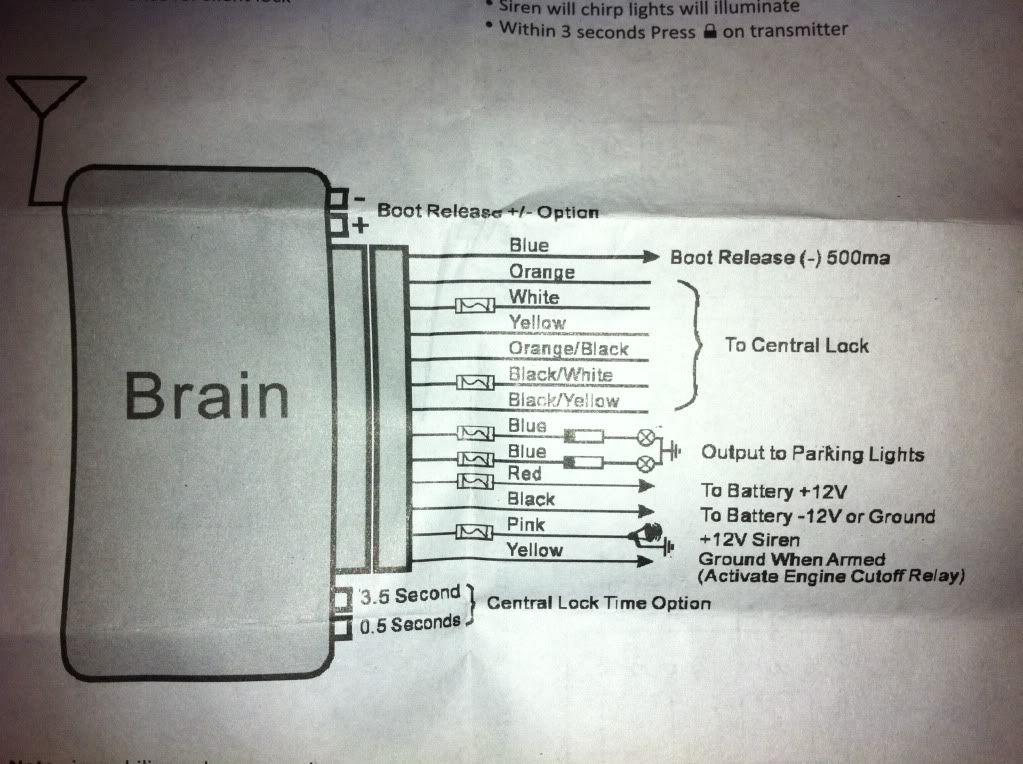
I have attached my modules wiring diagram below.
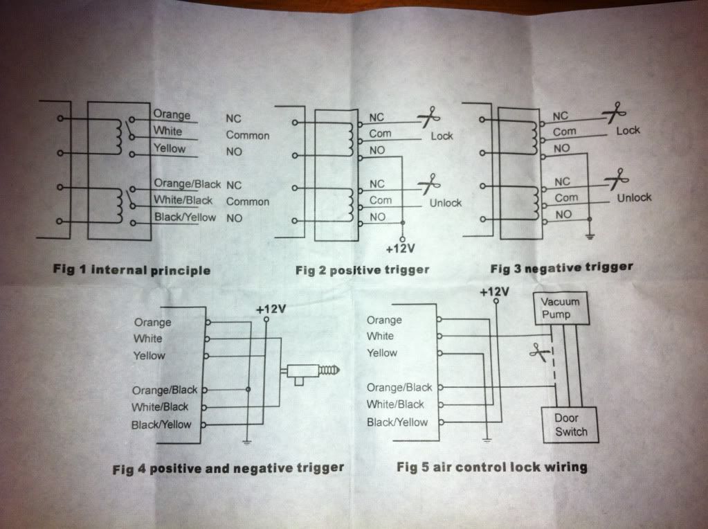
The seller has recommended that i connect the 'white' to lock and the 'white/black' to unlock (module wires). He also recommended i "attach the 2 yellow wires to power", maybe this is whats going wrong??
Ive got the unit powered up and grounded (i disconnected it from the centrsl locking) and it is still making the exact same noises if i press lock or unlock on the remote. The same thing happened when i wired the following way:
Car Wire ** Module wire ** Function
Brown ** Black ** Ground
Green/Black ** White ** Lock
Yellow/Black ** White/Black ** Unlock
- Constant 12V power was extended from red antenna wire
- The modules black (ground) wire was ground behind a bolt/washer in boot. Not grounded with brown (ground) from cars wiring.
- The 2 yellow module wires were attached to 12V constant power as instructed by the ebay seller. But when theyre not attached, i see no difference.
Note: The central locking works fine by key.
I tested whether or not the green/black actually locked the central locking and the Yellow/black actually unlocked. When they were individually seperated i could see that they were definitely responsible for locking and unlocking the central locking at the boot. When disconnected i could still use the central locking from the passenger door (drivers door lock hasnt worked from outside in months), and just the boots central locking is affected, as i expected.
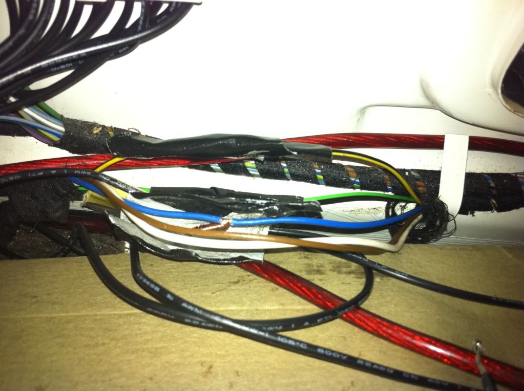
The cars yellow/black wire at first could not be found. Only the black/green could be found in the connector in the boot.
But looking underneath (running along the floor of the boot) there was a small bundle of wires, where i found both in there. So i used them directly from there. Just sniped them, stripped the end a little joined them, and added the appropriate wire from module (as i dont have any way of stripping the wire while leaving them connected). Then i used electrical tape to insul;ate the connected wires. This is how my stereo is done, and i have never had a problem with it.
Any ideas what i am doing wrong??
Someone mentioned in my other post that i might need to 'sync' my remotes? I'm not sure if this is it, as when i press a button on my remote, i can hear the module making noises and doing something. The problem is, it just doesnt lock or unlock the central locking
Also i need to clarify which wiring diagram (type of triggering) i should definitely be following.
Thanks heaps
John
Re: Central locking: Positive or negative trigger???
They are negatively triggered. That means the lock button grounds a wire to tell the central locking control unit to lock or unlock the car.Bm Guru wrote:Are the central locking systems in the e28 (1986 535i) "positively triggered" or negatively triggered??
If the locks are negatively triggered then you want to use Fig 3. which means yellow and yellow/black are grounded.The seller has recommended that i connect the 'white' to lock and the 'white/black' to unlock (module wires). He also recommended i "attach the 2 yellow wires to power", maybe this is whats going wrong??
demetk wrote:If the locks are negatively triggered then you want to use Fig 3. which means yellow and yellow/black are grounded.The seller has recommended that i connect the 'white' to lock and the 'white/black' to unlock (module wires). He also recommended i "attach the 2 yellow wires to power", maybe this is whats going wrong??
Thank you so much!!!
No one could tell me how to figure out what figure 3 actually meant. I could see that the yellow and black yellow wires needed to be connected to either power or ground, i couldnt understand the schematic diagram
I'll go try it now.
Thank
Thank you so much Demetk!
My keyless entry now works!!!!
I did what you said and followed fig 3. I grounded the modules yellow (actually has 2 so i grounded both) and yellow/black wires.
The only problem is i need to press the 'unlock' button on the remote to actually lock the car, and the 'lock' button on the remote to unlock the car.
My wiring is as follows:
CAR WIRE ** MODULE WIRE ** FUNCTION
Green/Black ** White ** Lock
Yellow/Black ** White/Black ** Unlock
n/a ** Red ** =12v constant power from antenna
Brown ** Black ** Ground
n/a ** 2 x Yellow ** Ground
n/a ** Black/Yellow ** Ground
I think i have something back to front, anyone have any ideas what?
Best Regards
John
I just spoke to the ebay seller, and he told me if my remote buttons are functioning back to front, just swap the module wires around, i.e. swap 'white' module wire around with 'white/black' module wire.
Once i done this nothing happened.
then i opened my boot, and pressed the remote 'lock' button right next to the module, and suddenly it all started working!!!!
I have tested it out and get really decent range! I am so happy because my drivers lock wouldnt work from the outside, so no more walking around to unlock from the passenger side or boot!!!!!!
This changes my life!!!
So below is the final and correct wiring for this unit:
CAR WIRE ** MODULE WIRE ** FUNCTION
Green/Black ** White/Black ** Lock
Yellow/Black ** White ** Unlock
n/a ** Red ** =12v constant power from antenna
Brown ** Black ** Ground
n/a ** 2 x Yellow ** Ground
n/a ** Black/Yellow ** Ground
If you are after the exact same keyless entry kit that i bought you can find it on Ebay.com.au from a seller named "rapid-electronics" for AUD$49 at:
http://cgi.ebay.com.au/REMOTE-KEYLESS-E ... 51931ee860
The after support is great, he even gives his mobile phone number!
Im now thinking of buying the Power Windows System with Auto close (featuring protection circuit) for all 4 doors plus sunroof for AU$49. He said its much easier to fit, compared to the keyless entry.
The last thing im trying to figure out, is how do i connect this keyless entry module to my cars indicator lights so they flash when the doors are locked and unlocked using the remote? There are 2x Blue wires on the module that are designed for exactly this, but im trying to figure out how it works.
I'm starting to think that because the central locking system is a negatively triggered system, maybe all i need to do is put the 2 blue module wires into the tail lights 'ground' wire which im assuming is the brown one if its the same as the centraql locking (1 into each side). Im not sure if once plugged in would ALL indicators flash when the remote keyless entry is pressed, or just the indicators in the tail lights?
Thanks heaps everyone!
Regards
John
-
John Boelte
- Posts: 270
- Joined: Sep 18, 2006 2:48 PM
- Location: Indianapolis, IN
That's pretty cool, I'm glad you got it working. :bannana:
I think you're going to have to figure out how to supply power to the lights to get them to flash. They are already grounded; they get power sent to them from the vrious switches and relays. If you're mountig everything in the trunk, you could probably install a relay between your control unit and a power source and tap into one of the marker light wires. Powering one of the marker lights should back feed to the others connected in the circuit up to the switch or relay that controls them.
I think you're going to have to figure out how to supply power to the lights to get them to flash. They are already grounded; they get power sent to them from the vrious switches and relays. If you're mountig everything in the trunk, you could probably install a relay between your control unit and a power source and tap into one of the marker light wires. Powering one of the marker lights should back feed to the others connected in the circuit up to the switch or relay that controls them.
John Boelte wrote:That's pretty cool, I'm glad you got it working. :bannana:
I think you're going to have to figure out how to supply power to the lights to get them to flash. They are already grounded; they get power sent to them from the vrious switches and relays. If you're mountig everything in the trunk, you could probably install a relay between your control unit and a power source and tap into one of the marker light wires. Powering one of the marker lights should back feed to the others connected in the circuit up to the switch or relay that controls them.
Thanks John,
I figured out how to connect the indicators to make them flash when the keyless entry is locked or unlocked.
I just turned the indicator on, and used a test light to check which wire was causing the test light to flash on and off. As expected only 1 of the 6 wires caused this.
The colour of each indicator wire in the tail / brake lights are noted below:
LEFT side:
Blue/red wire
RIGHT side:
Blue/Black
So they're the outer most (top row) wires.
I just connected each of them to my keyless entrys 2 x blue wires, and now my indicators flash once when my doors lock, and twice when they unlock. It's pretty cool. Can't believe how easy it was to figure out and hook up.
Next mods on the list:
1. Immobiliser (came with keyless entry)
2. Auto lift windows which will close automatically when i lock the car using keyless entry remote
I also have an e34 540i. Does anyone know if the central locking is:
1. Also a 'negative' trigger system
and
2. Can it all be installed from the boot (i.e. trunk lol) again.
Regards
John
1. From what I remember doing my e34, I think they're positive trigger.I also have an e34 540i. Does anyone know if the central locking is:
1. Also a 'negative' trigger system
and
2. Can it all be installed from the boot (i.e. trunk lol) again.
2. This e34 system is very different than the e28. You will need to trigger the general module which is under the driver's rear seat. The general module then controls the relay module, in the same place, which activates the door locks.
For my 89 the ETM shows "A", "B" inputs to the general module. Looks like WS/GN (white/green) for the lock wire, WS/SW/GE (white/green/yellow stripe) for the unlock wire. Once you learn that it's all about inputs and outputs to the various modules it becomes a bit easier to figure out.
demetk wrote:
1. From what I remember doing my e34, I think they're positive trigger.
2. This e34 system is very different than the e28. You will need to trigger the general module which is under the driver's rear seat. The general module then controls the relay module, in the same place, which activates the door locks.
For my 89 the ETM shows "A", "B" inputs to the general module. Looks like WS/GN (white/green) for the lock wire, WS/SW/GE (white/green/yellow stripe) for the unlock wire. Once you learn that it's all about inputs and outputs to the various modules it becomes a bit easier to figure out.
Great, thank you i will remember the e34 colour wires to lock and unlock the e34 central locking. Do you think it is the same colour wires were used on all e34's?
Thank you
John
Keyless entry issues again
I just had keyless entry installed on my 1987 528E. It previously had some sort of keyless/alarm system installed which made it easier to tap into wires. Things worked okay for a few days. Until I got my onboard computer running. I mixed up the wires for the hazard and defogger this caused a pop. I replaced relays, blinker stalks, checked fuses, ect I got blinkers and hazards working again properly. My keyless entry worked one last time before going kaput. When I say kaput nothing is working. I can use the locks manually with a key one at a time, but that's it. I purchased three central lock control units plus I had one from a parts car the first one made a relay click when I tried the keyless entry, but nothing happens. The others are doing absolutely nothing. I've taken proper precautions by disconnecting the battery before I install each central lock brain.
I've gotten to the point where I'm about to forgo the factory actuators. I can install 8 pound actuators with a 7/8" of throw there are other throw lengths available. I figure if I wire this up to the aftermarket brain for my keyless entry I can bypass all of the issues that I'm having.
I've been told by my installer this may be an issue because of BMWs "deadbolt" has anyone had experience installing aftermarket actuators for their locks?
When I had central locking problems on my 88 it had so many issues, that I was about to do what you are contemplating. But my final Hail Mary attempt of ripping out the keyless entry wired to the trunk wiring and installing a more state of the art system at the controller, miraculously worked. 
Have you tried activating the locks by probing the lock/unlock wires at the controller?
Have you tried activating the locks by probing the lock/unlock wires at the controller?
-
Boxer Metal
- Posts: 2
- Joined: Sep 15, 2013 3:39 AM
- Location: Chico, CA
- Contact:
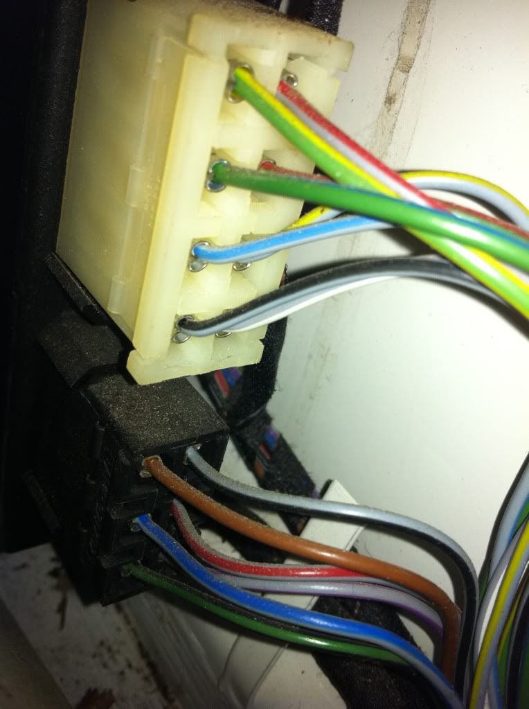
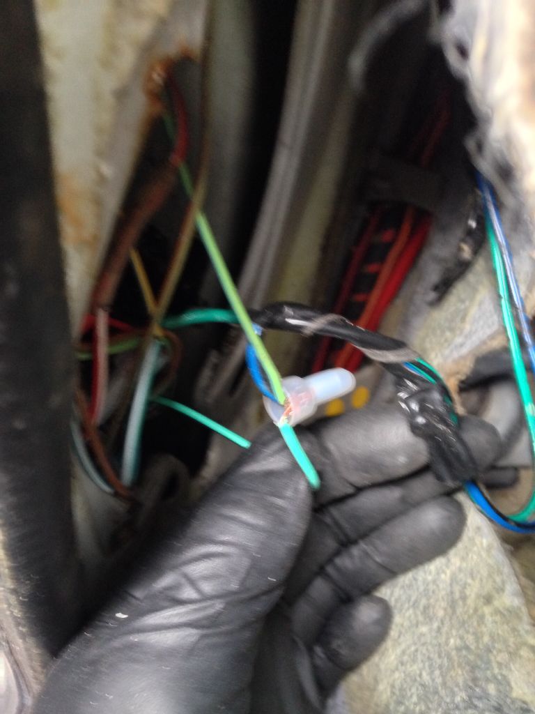
Boxer Metal wrote:The wife's car will only unlock and lock the doors from the trunk. I installed one of these remote door systems and the unit clicks like it's working but none of the actuators work.
Do I have a deeper problem?
I learned When you add keyless entry to an E28 it activates off the ground. Most cars activate off the positive. Sorry this picture sucks. I took it when I was removeing the recently installed keyless system. It's shows the blue and green wires coming from the keyless module. They connect behind the drivers speaker. Make sure you have them connected properly.
Re: Central Locking System
I just want to say thank you all for your inout no matter how old. I just did it on my e28 in July 2023 and I wouldn't have done it without you guys.
Thank you
Thank you