Useful Motronic 1.0 Info/Eprom Information 10/22 How I found Cold Start Values

E28 technical advice asked and given! Troubleshooting, modifications and more.
Post Reply
LeiseyJr
Posts: 1527
Joined: Dec 22, 2013 10:11 PM
Location: Houston,Tx

Useful Motronic 1.0 Info/Eprom Information 10/22 How I found Cold Start Values

Post by LeiseyJr »

E28 M1.0 Information
By Samuel Leisey


Hello, welcome here are my notes and info I have learned trying to tune my own e28 as well as my curiosity of how it works.
Keep in mind, I'm just a someone with a laptop. Still learning a lot, and a lot of stuff I still don't know. This will be a dump of info for others to learn from hopefully get some people who are smarter then me can add to this. It will also be a great reference to myself to have here.

!WORK IN PROGRESS!
Still need to add 6/26/2021
Quick Links to other excerpts/rants:
Oxygen Sensor Purpose for Motronic
Why M1.0A sucks to most people
ignition numbers
24 vs 28 Pin
Hex Fuel Numbers converted to AFR
writing to an eprom
Miller WAR Writeup
Table of Tables in Motronic
Formula to Convert Miller Ignition Values to Hex or vice versa
Converting Miller/Hex to AFR/Tuning WOT Fuel


How Motronic Works/Basic Understanding of Eprom Tuning


So. Motronic 1.0. The magic made by Bosch that runs your car. How does it work?
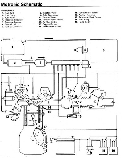
Imageunnamed (1) by Kurvenkamph Motorsport, on Flickr

Well those are the parts, it needs to make the car run.

Key Components that:
AFM w/ built in air temp sensor- measures the volume of air coming in with a potentiometer and a reference voltage
Crank Sensor- tell engine position and RPM
3 position TPS- Idle, Part Throttle and WOT
Narrowband Oxygen Sensor- Reads 14.7 AFR
Coolant Temp Sensor: tells engine how good it looks, I mean how hot/cold it is
Fuel Injectors: controlled by DME (grounding them and it batch fire not sequential)

Motronic is so simple, they're all pretty essential but those are the main basic ones.


What's on the chip thing people are selling?
We know, thanks to wondeful people that are way smarter than me like Jim Conforti and Mark D. you can change what the DME does with by just installing a chip with coding.

So what is on the chip? Great Question. Well with the file I'm about to give you and a free .bin tool you can see what the hell is on on there.
https://drive.google.com/drive/folders/ ... sp=sharing

If you download the stock24pin.bin you can view that on a browser tool:
https://hex-works.com/eng
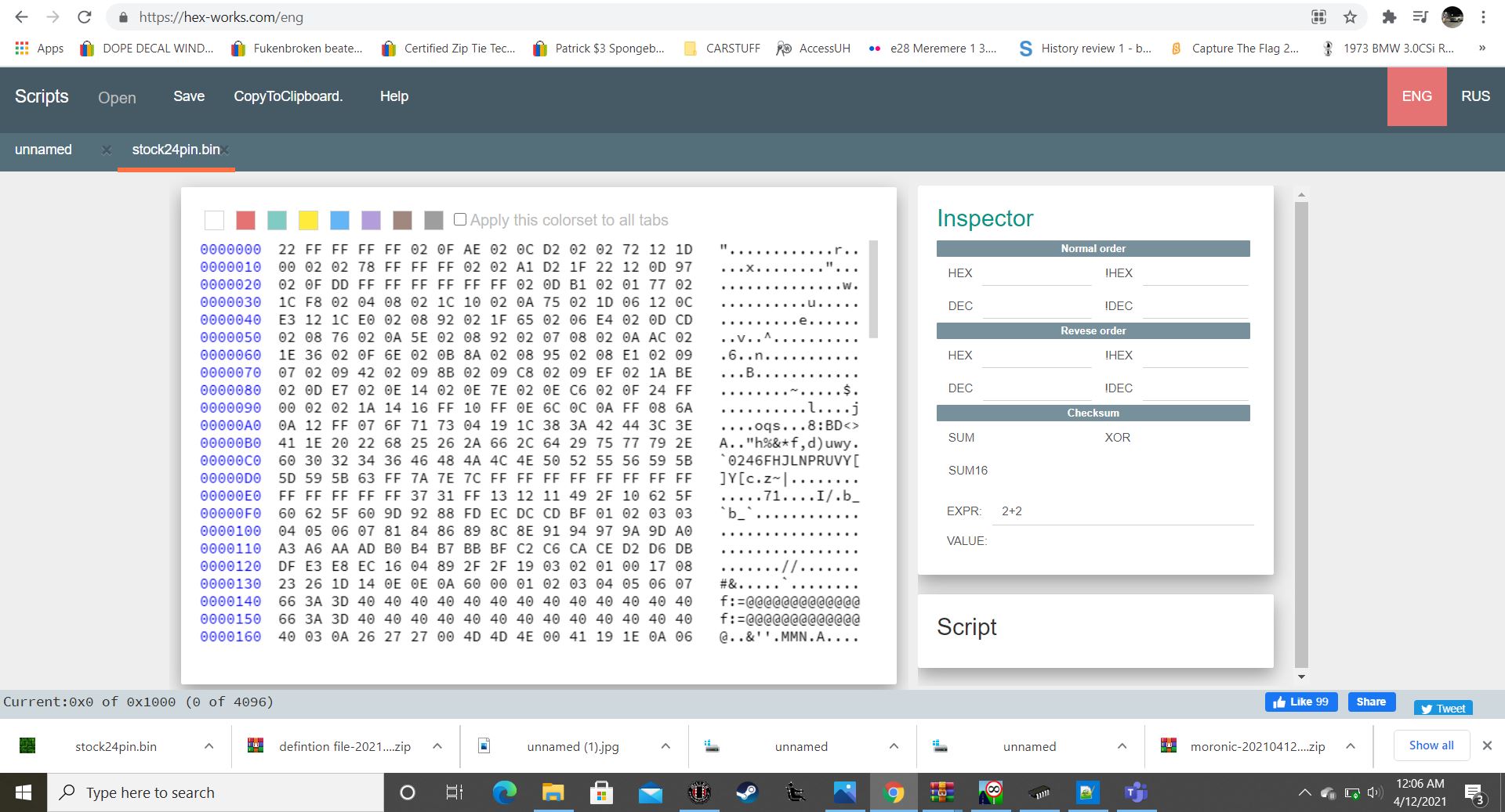

Imagealienlanguage by Kurvenkamph Motorsport, on Flickr

Well, that's a lot of letters and numbers... well let's go to line 490 and go to address 492. The value there is 7B, what is 7B. The bin file is being displayed in hex right now. So let's convert it to decimal, something we are used to. Maybe that will make more sense. Alright the value is 112? If we keep going we see that the values are around 110-140. From

Because I have used the Miller WAR software something sticks out. I am seeing a group of 110-140 numbers. Okay that looks familiar, and a lot of them. So that must be a part throttle map? So where are the load and rpm? What do the 110-140 numbers mean?
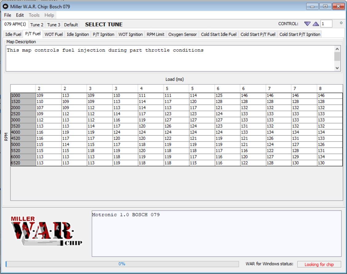
Imagem5stock by Kurvenkamph Motorsport, on Flickr

So we have a lot of question but it looks like from 492->521 there is a fuel map.


Alright, this is getting pretty complicated. Are there better tools to view/edit these .bin files? Great Question. There are:

WinOLS (demo is free can't save but can view files on there)
TunerPro

Let's start with WinOLS, when we open the file and tell it the ECU number it is highlighting the part throttle maps automatically.
Hey! We were right! We did find a part throttle map! Nice!
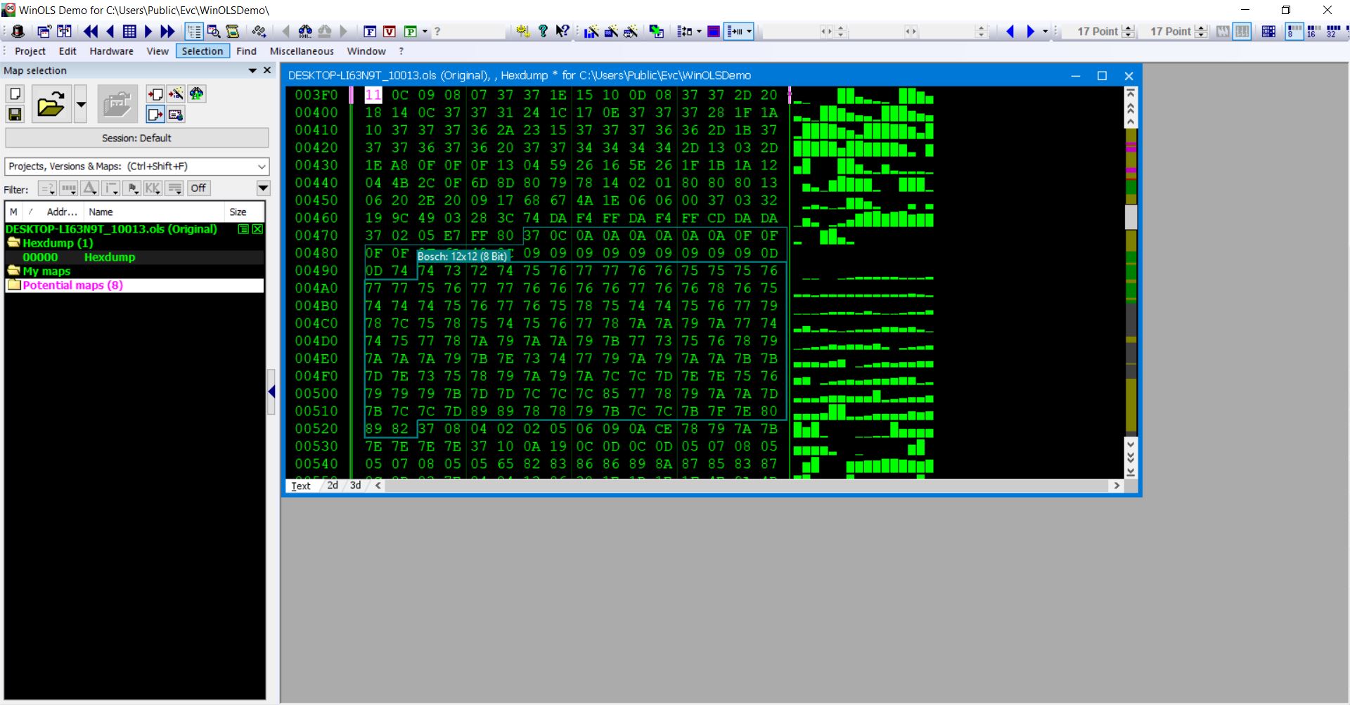


Imagewinols by Kurvenkamph Motorsport, on Flickr


It's highlighting some stuff before that? What is that? Well maybe converting it to decimal will help?
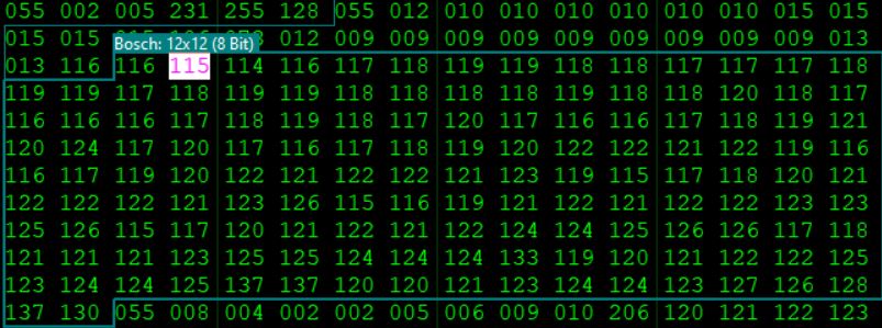
Imagewinols2 by Kurvenkamph Motorsport, on Flickr


It doesn't. Good news, those decimal values are definitely for a fuel map.


When I view that as 3D, it's a graph. So this is what the computer is seeing.
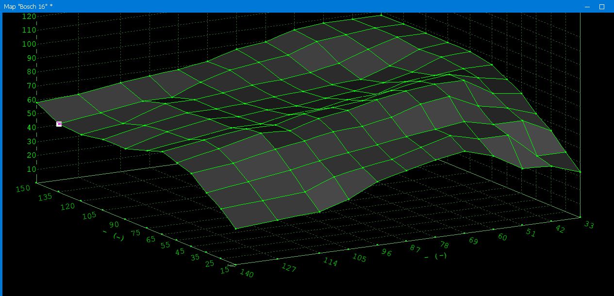

Image3d by Kurvenkamph Motorsport, on Flickr

So what the hell are the values????? Well we know the rpm axis is just RPM, but wtf is load in (ms) and what the are all those 120-130 values that we edit?

Some googling revealed a very helpful post:
https://www.bimmerforums.co.uk/threads/ ... c-ecus.72/


The code contains also the numerical information for load and RPM, just "above" the map. For example, in (one) Porsche code (951dme) you can find these following numbers above the fuel/ignition maps. 55 and 12 + 12 numbers of values and 73 and 12 + 12 numbers of values. I.e. 28 values (in decimal) before the fuel/ignition map values (144 numbers in decimal).

55 tells it is a RPM value and has 12 digits (numbers), 73 tells it is a load value and has 12 digits (numbers) => 12x12 matrix.

If the 12 digits after the 55 and 12 are (for example) as follows; 4 4 8 8 8 8 24 16 16 24 16 100, it tells what are the RPM values of the matrix. The last digit (100) is the most important one, it tells the max RPM value of the map, (256-100)x40 => 6240rpm. Then you start to calculate "backwards" using formula "previous value" - (current valuex40), i.e. the next value is 6240-(16x40)=5600rpm. The next one is 5600-(24x40)=4640rpm and so on. 40 is the constant used in Porche code.

4 4 8 8 8 8 24 16 16 24 16 100
===>
800 960 1120 1440 1760 2080 2400 3360 4000 4640 5600 6240 (rpm)

If the 12 digits after the 73 and 12 are (for example) as follows; 5 11 5 6 5 10 16 11 10 22 20 114
, it tells what are the load values of the matrix. The last digit (114) is the most important one, it tells the max load value of the map, 256-114 => 142 ms. Then you start to calculate "backwards" using formula "previous value" - "current value", i.e. the next value is 142-20=122 ms. The next one is 122-22 = 100 ms and so on.

5 11 5 6 5 10 16 11 10 22 20 114
==>
21 26 37 42 48 53 63 79 90 100 122 142 (ms)


Okay so we know what the values are in the computer and where we can see TWO of MANY other things in this code.

Still have a big question, what is load and what are the values we edit? Back to google:
Motronic needs exactly three things to calculate LOAD.

1) A signal from the air meter, normalized to "Q" airflow in kg/hr

2) A measure of current engine rpm "n"

3) A programmed injector size constant "Ki" (K sub eye)

LOAD aka Tl (Tee sub ell) is calculated as:

Tl = Q / (n * Ki)

LOAD is not just a representation of cylinder filling, but the
theoretical Injector Time Open (Ti, Tee sub eye) needed to reach
stoich (Lambda= 1) with the current injector setup assuming that
the motor is "perfect".

Which it isn't, hence there are fueling tables which are used as
multiplicative corrections to LOAD to reach the actual Ti.

Hope this clarifies.

Jim Conforti.


So this is really good information.

The computer knows what size injectors, so it can can calculate the volume of fuel coming in. The AFM also tells the computer the \volume of air coming in. So it can theoretically create the ideal injector time in relation to the AFM opening. So the values we edits are just correction numbers with no value.

Ideally 128 is 14.7, the computer can count 0-256. So at 128 there is no correction, that is 1 lambda.

Let's google some more, another great find here:
Fully explaining the formula Jim Conforti gave us above

MUST READ: https://rusefi.com/forum/viewtopic.php? ... 825#p29823


Okay so now we kind've understand what is happening.


Making Sense of the Chaos

You may be asking wait what about Tuner Pro? Well I wanted to give basic understanding how the hex worked before showing TunerPro.


TunerPro is a free tuning tool that allows someone to upload a .bin and view it after .xdf has parsed the file for the useful information. Making it easy to edit/view the alien language in the hex code.

Once you download TunerPro and the xdf file. You can view the stock 24 pin bin in a less alien way. Let's look at the part throttle map, since we already looked at that.
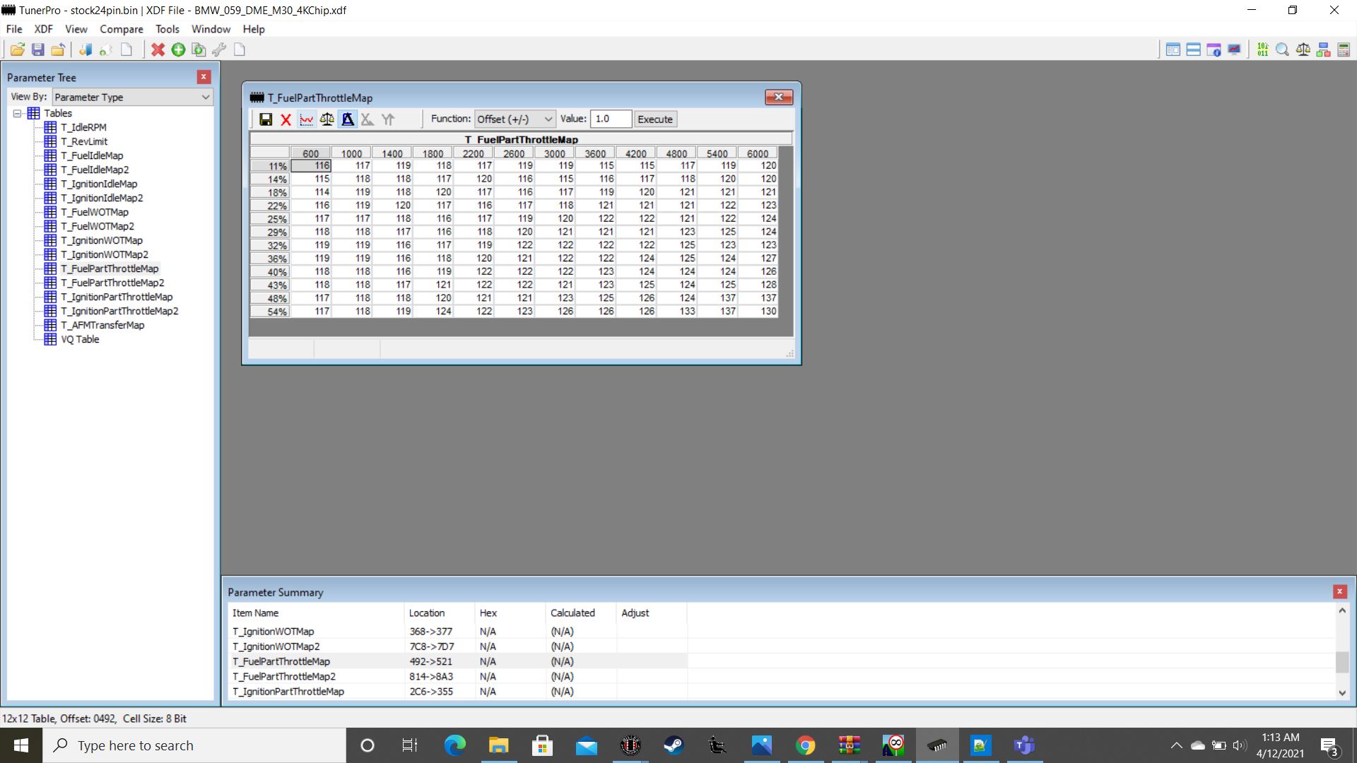
Imagetunerpro by Kurvenkamph Motorsport, on Flickr


and would you look at that at the bottom 492-521

So at this point, you can see all the .xdf file is doing is finding the values maps it is told point to and is converting them to English or normal values we understand.
Holy shit! There is a lot of stuff to edit!

I'll leave it here for now it is 1AM.


Still need to add 4/12/2021
Why M1.0A sucks
ignition numbers
24-28pin chip differences
writing to an eprom
miller WAR thing
Table of Tables in Motronic https://web.archive.org/web/20150731232 ... ptable.htm
Useful Links portion
Last edited by LeiseyJr on Oct 22, 2023 3:20 AM, edited 17 times in total.
tig
Posts: 9320
Joined: Mar 18, 2013 6:25 PM
Location: Durango
Contact:

Re: Morons Perspective of Mo(t)ronic

Post by tig »

:bow: :bow: :bow:
Shawn D.
Beamter
Beamter
Posts: 22104
Joined: Feb 12, 2006 12:00 PM
Location: Alpharetta, GA
Contact:

Re: Morons Perspective of Mo(t)ronic

Post by Shawn D. »

Great stuff -- keep it up!
LeiseyJr
Posts: 1527
Joined: Dec 22, 2013 10:11 PM
Location: Houston,Tx

Re: Morons Perspective of Mo(t)ronic

Post by LeiseyJr »

I want to separate this with the blob above.

24 vs 28 Pin DME


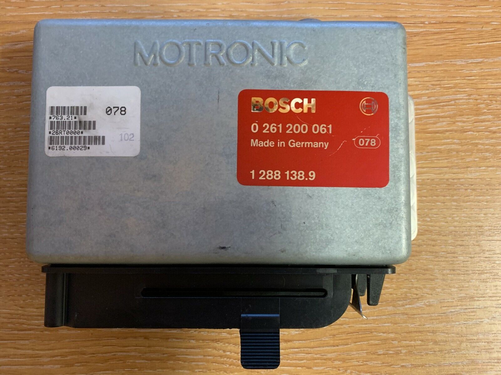
There are 2 EPROMs that are found in the 059 AND 061 DMEs. In my experience this is indicated by this white sticker. Every time I have opened up a DME with this sticker it has had a 28 pin. However I'm sure there are exceptions, out of 4 or 5 DMEs, I haven't experienced it yet.
Image


The 24 pin chip is a 2732A, this has 4kb of memory. It is considered the regular chip type, due to it being more common. This chip can be used in a 28 pin DME if you need to, the jumper at B70p needs to be removed and chip placed in the same orientation just furthest down, leaving 2 pairs of unused pins in the 28 pin holder.

The 28 pin DME uses a 27C64, or that's what I told my chip reader it was. More reading has shown that M1.3 might be a 27256. They are both read the same the only issue could be writing to the chip with a cheap programmer. These DMEs have the 28 pin holder and a jumper installed at B700.

This chip is 8kb, and the way it works. The top half of the .bin is filled with essentially blank space FF. The jumper at B700 tells the computer to only read the bottom half of of the chip, and that is where the same 4kb tune is stored.

Video showing how to see what eprom you have:
https://www.youtube.com/watch?v=yMxImC8bk44

https://members.rennlist.com/messinwith ... acking.htm
ignore this:
27C256

Back To The Top
Last edited by LeiseyJr on Jun 26, 2021 2:45 PM, edited 3 times in total.
Sparkeysf
Posts: 171
Joined: Feb 09, 2010 4:11 PM
Location: San Francisco, CA

Re: Morons Perspective of Mo(t)ronic

Post by Sparkeysf »

"The 24 pin chip is a 2732A, this has 4kb of memory. It is considered the regular chip type, due to it being more common. This chip can be used in a 28 pin DME if you need to, the jumper at B70p needs to be removed and chip placed in the same orientation just furthest down, leaving 2 pairs of unused pins in the 28 pin holder."

This is exactly the information I've been looking for. I bought a 24 pin D'Slvia performance chip a couple months ago only to discover my 059 DME has a 28 pin socket. I'll have to see if I can locate the jumper at B70p. When installing this chip, which side of the holder will have the unused pins?
LeiseyJr
Posts: 1527
Joined: Dec 22, 2013 10:11 PM
Location: Houston,Tx

Re: Morons Perspective of Mo(t)ronic

Post by LeiseyJr »

Sparkeysf wrote: Apr 18, 2021 11:50 PM "The 24 pin chip is a 2732A, this has 4kb of memory. It is considered the regular chip type, due to it being more common. This chip can be used in a 28 pin DME if you need to, the jumper at B70p needs to be removed and chip placed in the same orientation just furthest down, leaving 2 pairs of unused pins in the 28 pin holder."

This is exactly the information I've been looking for. I bought a 24 pin D'Slvia performance chip a couple months ago only to discover my 059 DME has a 28 pin socket. I'll have to see if I can locate the jumper at B70p. When installing this chip, which side of the holder will have the unused pins?
Image

https://www.lindseyracing.com/instructi ... n_Conv.pdf
Shows how to convert 24 to 28 pin. You aren't doing this but might still help. Just work backwards
LeiseyJr
Posts: 1527
Joined: Dec 22, 2013 10:11 PM
Location: Houston,Tx

Re: Useful Motronic 1.0 Info/Eprom Information

Post by LeiseyJr »

Oxygen Sensor
One of the more common misunderstood things is the function of the 02 sensor. When does the ECU refer to it and what is the significant of this data?

I see a lot of instances where people say the car knows it's running too lean or too rich, and when WOT the 02 sensor will adjust for changes such as exhaust or something alone those lines.

Some of that is true. The ECU does know when the car is running lean or rich, but to what extend it does not know. If you look at this narrowband that George Graves made awhile back can see what the DME is seeing.

https://www.youtube.com/watch?v=3cXUoNyFibI


So the point of this narrowband sensor is to detect stoicmetric, 1 lambda or also known as 14.7:1 AFR. Inside Motronic has a comparator, and it is constantly looking at the voltage from the 02. It is trying to maintain, .45 volts I believe. This is what the documentation I have for M1.3 is aiming for. Essentially it is trying to lean/richen the mixture all the time to make have an average voltage that represents stoichmetric. So at idle the car is always fluctuating between rich and lean as fast as the computer to allow, to make the average.

(Closed Loop)14:7:1 is perfect for a clean air idle, and emissions friendly light part throttle/cruising. It is trying to have a clean burn to make as little unburnt fuel and reduce CO and then the cat can work effectively at removing the NOX. This is when the DME refers to this.

(Open Loop)When letting off the gas and injectors are shut off, WOT and some instances of heavy part throttle the 02 sensor is ignored by the DME.

This is why a wideband is crucial for tuning and why the euro cars did not use an 02 sensor. BMW/Bosch just made the ecu so with a correctly adjusted AFM it would just hit the AFRs they wanted. To get better idle, response by running a bit richer sacrificing emissions.

This is not to say 02 sensor is a bad thing, but on M1.0 compared to M1.3 it is quite slow. Which I believe is why M1.0 idles rougher, it swings much greater in AFRs compared to M1.3. So I see why they held off for a bit. However since cars with an 02 sensor are getting feedback they can make adjustments to the fuel trim values which means they can adapt to changes. Whereas euro cars are like Alpha N with no feedback.

TLRDR: when tuning these cars, use a wideband. Factory 02 sensor is for minor variations in the air fuel mixture specifically at idle/light part throttle and ignored at heavy part throttle/WOT.

Back To The Top
Last edited by LeiseyJr on Jun 26, 2021 2:49 PM, edited 1 time in total.
Sparkeysf
Posts: 171
Joined: Feb 09, 2010 4:11 PM
Location: San Francisco, CA

Re: Morons Perspective of Mo(t)ronic

Post by Sparkeysf »

LeiseyJr wrote: Apr 19, 2021 1:56 PM
Sparkeysf wrote: Apr 18, 2021 11:50 PM "The 24 pin chip is a 2732A, this has 4kb of memory. It is considered the regular chip type, due to it being more common. This chip can be used in a 28 pin DME if you need to, the jumper at B70p needs to be removed and chip placed in the same orientation just furthest down, leaving 2 pairs of unused pins in the 28 pin holder."

This is exactly the information I've been looking for. I bought a 24 pin D'Slvia performance chip a couple months ago only to discover my 059 DME has a 28 pin socket. I'll have to see if I can locate the jumper at B70p. When installing this chip, which side of the holder will have the unused pins?
Image

https://www.lindseyracing.com/instructi ... n_Conv.pdf
Shows how to convert 24 to 28 pin. You aren't doing this but might still help. Just work backwards
So, I'll just desolder the jumper at B700, and orient the chip just as if it were positioned in a 24 pin socket. Perfect, that article clarifies everything. Thanks!
Tiit
Posts: 290
Joined: Oct 06, 2017 6:27 AM
Location: Canberra

Re: Useful Motronic 1.0 Info/Eprom Information

Post by Tiit »

Thanks for sharing. Following.
LeiseyJr
Posts: 1527
Joined: Dec 22, 2013 10:11 PM
Location: Houston,Tx

Re: Useful Motronic 1.0 Info/Eprom Information

Post by LeiseyJr »

Something I haven’t been able to get concrete information on is the ignition timing. I understand how it works.
Thanks to:
https://web.archive.org/web/20150731232 ... dvance.htm

Issue is knowing exactly what the calculation is.

I have verified the flywheel teethcount, with some laying around. Since these computers are “ML3.3” they should be able to do negative ignition timing. Assuming that constant 30 is the same.

https://www.matthewsvolvosite.com/forum ... hp?t=63998


But the tunerpro file Im pretty sure has the wrong calculation, so I will need to look at that.
Ju@n
Posts: 725
Joined: Apr 27, 2013 1:11 PM
Location: Uruguay

Re: Useful Motronic 1.0 Info/Eprom Information

Post by Ju@n »

LeiseyJr wrote: Apr 23, 2021 12:24 AM I have verified the flywheel teethcount
Tooth count changes in M20 and M30 engines, be wary of that :)
When trying to install an MS3 on my car, I found out my particular flywheel (and I think all M30 flywheels) have 135 teeth on them.
Keep the info coming! it's nice to see advancements in this area.
Btw spark info on tunerpro is pretty weird, some maps go near 50 degs of timing which is extreme I think :rofl:
tn535i
Posts: 5590
Joined: Jul 14, 2006 1:30 PM
Location: Middle Tennessee

Re: Useful Motronic 1.0 Info/Eprom Information

Post by tn535i »

I know timing is a huge part of the equation when making modifications to your map but I also know that TDC of cylinder #1 is NOT where the reference mark passes the sensor. So is it possible the timing advance numbers are based on the position of the mark and NOT the position of cylinder #1 as you might normally expect. Maybe like the offset in that first link posted just above. I can't remember how many teeth or degrees I found this to be... but I do think I remember it was AFTER cylinder #1 hit TDC. So if the timing is determined in reference to the sensor then weird and high numbers would make sense. Maybe in reality it is 50 -x (x = 22.5 or 30 or whatever) which sounds plausible to me.

I discovered this when we modified a later M20 SMF for use in an earlier eta and we needed to add the timing mark and based it on very careful measurements of the old M20 ring gear from an automatic. We must have come very close because the car runs like a champ.
LeiseyJr
Posts: 1527
Joined: Dec 22, 2013 10:11 PM
Location: Houston,Tx

Re: Useful Motronic 1.0 Info/Eprom Information

Post by LeiseyJr »

Hex Fuel Numbers converted to AFR

In relation to tuning WOT:
150 is a lot of fuel, like 10.0 AFR. Miller says it's 10 points adjustment = 1.0 AFR

But remember this number is an offset to whatever the base 128 number equals to. It isn't directly related to AFR.

So for WOT,
I haven't found this true. Increments of 5 can be big, but throwing 10 at it doesn't hurt. Also around 5200, you have to start leaning it out. On the conforti and some other chips as well as what I have found. It is roughly 10 points less. So for instance if you are at 134 at from 2200-4800, when you hit 5200 you need to drop it down to 124 and stay relatively close to that until redline. If you stayed at 134 it'd get way too rich.

My point is, different areas take different numbers and it isn't always consistent.
Back To The Top
Last edited by LeiseyJr on Jun 26, 2021 2:03 PM, edited 1 time in total.
LeiseyJr
Posts: 1527
Joined: Dec 22, 2013 10:11 PM
Location: Houston,Tx

Re: Useful Motronic 1.0 Info/Eprom Information

Post by LeiseyJr »

Miller Ignition Number:
If you want to convert an eprom to be used on your Miller WAR Chip, Or compare your Miller Tune to another chip.

For fuel just copy and paste, since they're raw values.

This is the conversion Miller uses to convert from Decimal to BDTC, which I don't think it's right. But whatever.

X= Hex Ignition Number
(X*0.75)-22.5 = BDTC
Back To The Top
Last edited by LeiseyJr on Jun 26, 2021 2:23 PM, edited 1 time in total.
Nothintoseeere
Posts: 57
Joined: Apr 23, 2021 5:27 PM
Location: U.k

Re: Useful Motronic 1.0 Info/Eprom Information

Post by Nothintoseeere »

Nice.
ElGuappo
Posts: 8130
Joined: Feb 12, 2006 12:00 PM
Location: Sacramento, CA
Contact:

Re: Useful Motronic 1.0 Info/Eprom Information

Post by ElGuappo »

This is one of the best posts I've seen in a long time Sam, keep up the good work. :up:
RonW
Posts: 5321
Joined: Feb 12, 2006 12:00 PM
Location: Long Island, NY

Re: Morons Perspective of Mo(t)ronic

Post by RonW »

LeiseyJr wrote: Apr 16, 2021 3:55 PM24 vs 28 Pin DME

The 24 pin chip is a 2732A, this has 4kb of memory... This chip can be used in a 28 pin DME if you need to, the jumper at B70p needs to be removed and chip placed in the same orientation just furthest down, leaving 2 pairs of unused pins in the 28 pin holder.
I was curious about this, because the 8051 has built-in PROM. I was wondering if that PROM was used in the 24-pin units, but its contents moved into the memory chip for the 28-pin units. If that were the case, the processor in a 28-pin unit would contain no code, and the 24-pin chip wouldn't work, because it wouldn't contain the code that would be in the processor in a 24-pin unit.
Mike W.
Posts: 27230
Joined: Feb 12, 2006 12:00 PM
Location: California Whine Country

Re: Useful Motronic 1.0 Info/Eprom Information

Post by Mike W. »

Now this is just an outstanding post. I've been following it, understand only parts of it, but can fully appreciate it. I can't disagree with the change in title, but if the original was a Morons Perspective then I'm down in the slug perspective. Great work! :up:
LeiseyJr
Posts: 1527
Joined: Dec 22, 2013 10:11 PM
Location: Houston,Tx

Re: Morons Perspective of Mo(t)ronic

Post by LeiseyJr »

RonW wrote: Jun 25, 2021 1:14 PM
LeiseyJr wrote: Apr 16, 2021 3:55 PM24 vs 28 Pin DME

The 24 pin chip is a 2732A, this has 4kb of memory... This chip can be used in a 28 pin DME if you need to, the jumper at B70p needs to be removed and chip placed in the same orientation just furthest down, leaving 2 pairs of unused pins in the 28 pin holder.
I was curious about this, because the 8051 has built-in PROM. I was wondering if that PROM was used in the 24-pin units, but its contents moved into the memory chip for the 28-pin units. If that were the case, the processor in a 28-pin unit would contain no code, and the 24-pin chip wouldn't work, because it wouldn't contain the code that would be in the processor in a 24-pin unit.
I was reading up on the 8051 and wondering the same thing myself at first. I believe this is not the case for the 28pin 059 for two reasons. The upper half of the stock 28 pin chip for the 059 is essentially filled with nothing (FFs) and I have ended up with a 28 pin DME that had a 24 Dinan chip in it.

It is interesting they didn't use the extra memory.

My 28 pin 061 DME chip they might have, I was rushing when using his reader and used the wrong chip selection. So I got a 32KB file and I cannot convert it. But the upper half of the .bin I got is not filled with FFs
LeiseyJr
Posts: 1527
Joined: Dec 22, 2013 10:11 PM
Location: Houston,Tx

Re: Useful Motronic 1.0 Info/Eprom Information

Post by LeiseyJr »

Glad people are liking it. Motivation I need to keep adding stuff.
LeiseyJr
Posts: 1527
Joined: Dec 22, 2013 10:11 PM
Location: Houston,Tx

Re: Useful Motronic 1.0 Info/Eprom Information

Post by LeiseyJr »

So this is why people say M1.0A sucks

https://www.youtube.com/watch?v=INtRH46B2Ls

Notice the slow AFR "swing". Swing being how much it deviates as it tries to average 14.7. I have not found a way to tune this out. I could have the car idling perfectly at 14.7 with the 02 sensor turned off or unplugged. As soon as it is reenabled or plugged in it will swing like that, just how the DME is. Why they never have a buttery smooth idle, unlike M1.3 or with the euro DME. This swing is also apparent at part throttle but never perceivable.


Which is why for the euro cars, Alpina etc, decided to use the 061. Could get smoother performance as well as not just program the DME to hit the values they wanted. They didn't need to maintain 14.7 Anyway to keep the cat happy.

Notice how the AFR never swings more than .1 or so. It isn't reacting just doing. This is about how M1.3 idles.

https://www.youtube.com/watch?v=3iPAUc7YOdI

Later as emissions became more stringent and the computers got faster, they could/had to use the 02 sensor for all markets and models. As well as the added bonus of using the 02 sensor to adjust overall trims, if car got leaner or richer. This is the adaptability part of the 02 sensor.

Back To The Top
Last edited by LeiseyJr on Jun 26, 2021 2:32 PM, edited 1 time in total.
LeiseyJr
Posts: 1527
Joined: Dec 22, 2013 10:11 PM
Location: Houston,Tx

Re: Useful Motronic 1.0 Info/Eprom Information

Post by LeiseyJr »

Added quick links and a way to get back to the top easily. 6/26/21
Mike W.
Posts: 27230
Joined: Feb 12, 2006 12:00 PM
Location: California Whine Country

Re: Useful Motronic 1.0 Info/Eprom Information

Post by Mike W. »

LeiseyJr wrote: Jun 26, 2021 12:14 PM So this is why people say M1.0A sucks

https://www.youtube.com/watch?v=INtRH46B2Ls

Notice the slow AFR "swing". Swing being how much it deviates as it tries to average 14.7. I have not found a way to tune this out. I could have the car idling perfectly at 14.7 with the 02 sensor turned off or unplugged. As soon as it is reenabled or plugged in it will swing like that, just how the DME is. Why they never have a buttery smooth idle, unlike M1.3 or with the euro DME. This swing is also apparent at part throttle but never perceivable.
From readings years ago I believe that swing is intentional, that it worked better for emissions at the time. Something to do with the cat absorbing, then burning off oxygen.
LeiseyJr
Posts: 1527
Joined: Dec 22, 2013 10:11 PM
Location: Houston,Tx

Re: Useful Motronic 1.0 Info/Eprom Information 6-26 Added/Updated

Post by LeiseyJr »

Tiit
Posts: 290
Joined: Oct 06, 2017 6:27 AM
Location: Canberra

Re: Useful Motronic 1.0 Info/Eprom Information 6-26 Added/Updated

Post by Tiit »

ECU is not targeting 14.7 fuel ratio. Catalytic converter does not work with perfect 14.7 fuel ratio. It requires slightly lean and slightly rich conditions for each stage to work efficiently. That’s why o2 sensors appeared on cars with catalytic converters. Even cars with carburettors had o2 sensors if catalytic converters were fitted.
MyE24
Posts: 94
Joined: Apr 16, 2021 10:43 AM
Location: California

Re: Useful Motronic 1.0 Info/Eprom Information 6-26 Added/Updated

Post by MyE24 »

Excellent info.
Is there any way you could film the M1.0 A/F gauge while driving at freeway speeds?
I’m curious to see what it’s doing under a constant load.
LeiseyJr
Posts: 1527
Joined: Dec 22, 2013 10:11 PM
Location: Houston,Tx

Re: Useful Motronic 1.0 Info/Eprom Information 6-26 Added/Updated

Post by LeiseyJr »

Tiit wrote: Jun 26, 2021 11:25 PM ECU is not targeting 14.7 fuel ratio. Catalytic converter does not work with perfect 14.7 fuel ratio. It requires slightly lean and slightly rich conditions for each stage to work efficiently. That’s why o2 sensors appeared on cars with catalytic converters. Even cars with carburettors had o2 sensors if catalytic converters were fitted.
https://youtu.be/tVCdRcDNfKM?t=726
turn on auto translate
LeiseyJr
Posts: 1527
Joined: Dec 22, 2013 10:11 PM
Location: Houston,Tx

Re: Useful Motronic 1.0 Info/Eprom Information 6-26 Added/Updated

Post by LeiseyJr »

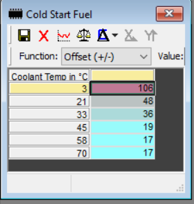
Cold Start Fuel Values are at 0x55E to 0x563
will have a lengthy post soon
Shawn D.
Beamter
Beamter
Posts: 22104
Joined: Feb 12, 2006 12:00 PM
Location: Alpharetta, GA
Contact:

Re: Useful Motronic 1.0 Info/Eprom Information 6-26 Added/Updated

Post by Shawn D. »

LeiseyJr wrote: Oct 21, 2023 11:13 AM Cold Start Fuel Values are at 0x55E to 0x563
will have a lengthy post soon
Thanks for regularly updating your endeavors!
LeiseyJr
Posts: 1527
Joined: Dec 22, 2013 10:11 PM
Location: Houston,Tx

Re: Useful Motronic 1.0 Info/Eprom Information 10/21 Finding a Table

Post by LeiseyJr »

One of the persistent issues with the M535i was its less-than-optimal starting performance. It consistently cranked up, but it took around 10 to 15 seconds to stabilize the idle during cold morning starts. Hot starts showed a slight improvement in the time it took to stabilize. I was accustomed to the near-instantaneous idle settling I experienced with the Motronic system in my other car.

Eventually, this issue became bothersome enough to warrant a closer look (a week ago). The tune in the car is custom, but I used an Alpina B10 tune as a base map to start. Reverting to the stock tune immediately resolved the problem, confirming that the root cause lay within the tuning file.

This past week, I acquired a new work laptop. Unfortunately, I cannot provide screenshots of the Miller Software until I have it reinstalled and set up. However, I recalled that the tuning software for the WAR chip included a Cold Start Fuel table for editing. None of the available XDFs contained this specific table. Upon further examination, it became evident that there were differences in this aspect.

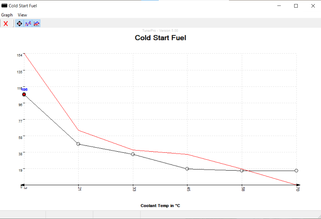
Here's a visual representation:
ImageCold Start Fuel Differences 061 by Kurvenkamph Motorsport, on Flickr

The black line represents the Alpina B10 cold start values, while the red line depicts the stock 10:1 cold start values. Armed with this knowledge, I reloaded my tune onto the 061 DME, which contains a Miller WAR chip, but I replaced the cold start values with the stock 10:1 values. This change effectively eliminated the surging issue following startup.

However, a significant challenge remains. I have only one Miller WAR chip and one 28-pin 061 DME. My objective is to write this corrected file to the original 061 24-pin DME in the car using a standard EPROM chip.

I needed to define where these addresses were in the .bin, so I could make a table in the XDF file for TunerPro to edit it. It didn't really matter which tune I started with, but I used the stock one for this.

I knew in the Miller software, the cold start values I could see were:

154, 64, 41, 36, 19, 0

If you are familiar with these .bins, they are binary files and are typically viewed in hexadecimal. Sometimes numbers are converted, for instance, the ignition numbers. However, I had a feeling those were raw decimal numbers.

So the first step was converting that to hexadecimal.

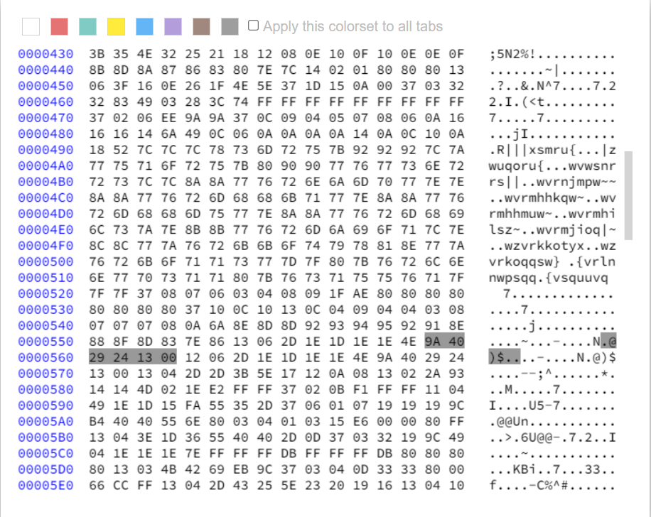
9A, 40, 29, 24, 13, 00

Great, I had the string of characters I needed to look for.

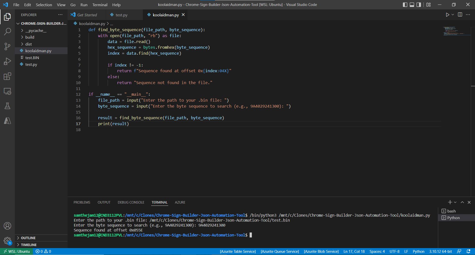
So I wrote a quick Python Script with the help of AI to parse a bin file for a specified sequence of numbers, just to speed this up in the future. I need to make a GUI for this, probably with tkinter.

Imagepythoncode by Kurvenkamph Motorsport, on Flickr

But it told me it was at 0x055E, and sure enough. So awesome the tool worked, and I knew where the cold start values were now!

Imagebin by Kurvenkamph Motorsport, on Flickr

After some fiddling with Tunerpro:
ImageAlpina Cold Start Fuel by Kurvenkamph Motorsport, on Flickr

I can now edit my starting fuel values on a regular chip!! :ohyeah:


Cold Start P/T Table were found same way and address for those is: 0x457->0x45C
Post Reply