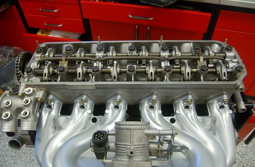
Noob M30B35 Build
I like PM's about as much as I like dirty door jambs. Sorry I did not reply. Here's what you posted, since there's nothing private about it:buzby wrote:PM sent, please answer
I did not remove anything from the housing. I will not be using that housing (I have a B34 block now and will be using a B34 housing that I am NOT powder coating).Hi, I am doing a similar build on an S38 B35. Noted you powder coated your oil filter housing. Did you have any issues with any of the plastic non return/by pass valves in the housing during the powder coating drying process? Or did you remove them prior to coating?
I am considering powder coating my housing with has a non metallic disc as by pass valve and cannot easily be removed.
Also, did you powder coat your cylinder head?
Thanks.
I did not powder coat the head.
No progress on this project for a while. I wanted to get Maytag sorted first. Now that it has a stereo and the interior is dry I'll likely start back on this project.
A few weeks ago Cruzin Performance got my rebuilt and flow-tested 24lbs injectors back to me.
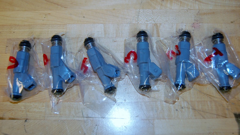
I also had them rebuild/flow-test a set of 19lbs injectors that I'll keep as a backup/future project.
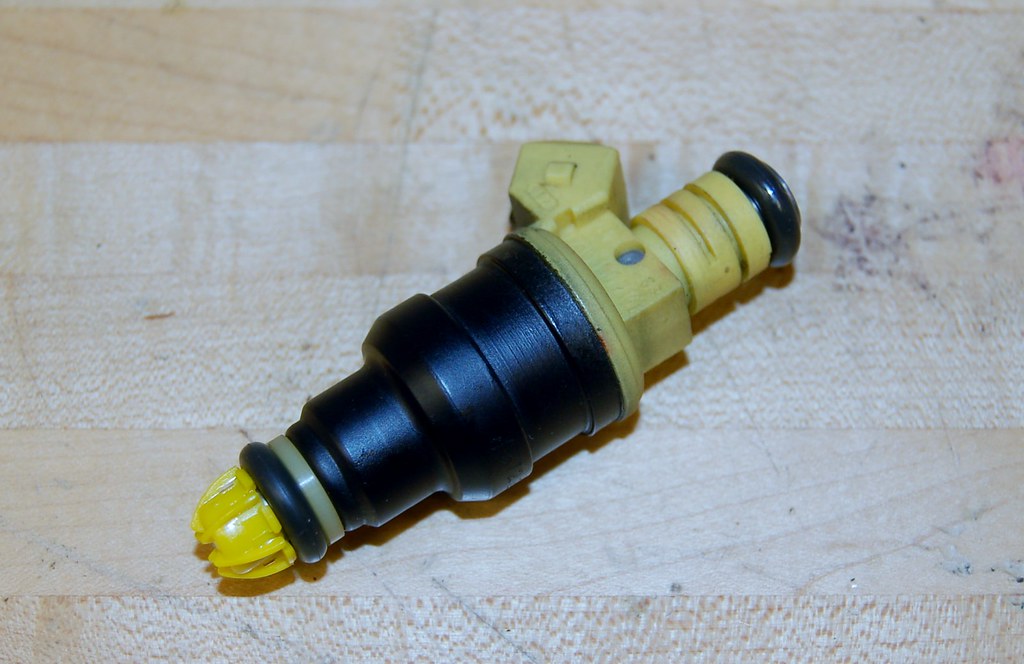
A few weeks ago Cruzin Performance got my rebuilt and flow-tested 24lbs injectors back to me.

I also had them rebuild/flow-test a set of 19lbs injectors that I'll keep as a backup/future project.

-
Das_Prachtstrasse
- Posts: 5616
- Joined: Sep 10, 2006 7:06 AM
- Location: Melbourne, Doooown Under
Haven't checked into this thread for a while, but I like what I see. I'm hankering to get this trip of mine out of the way so I can redirect funds into my own high comp b35/ITB build, as it's been pushed aside for the time being. Bet you can't wait to install each one of those fasteners! I had a blast putting my ITB's back together with all new painted and coated bits, doing the same with the complete engine is going to be like Christmas.
Subscribed.
Subscribed.
Today's job was to refresh the wiring harness.
I have two. One that came from the donor 735i and another that I purchased from a member here that came from an E34. The E34 harness is in much better shape so that's what I'm basing on.
However, even it has old, hard wire insulation that cracks when bent. Today I set about removing all of that and re-wrapping using F4 tape. I've never used F4 tape before, but it seems like pretty awesome stuff!
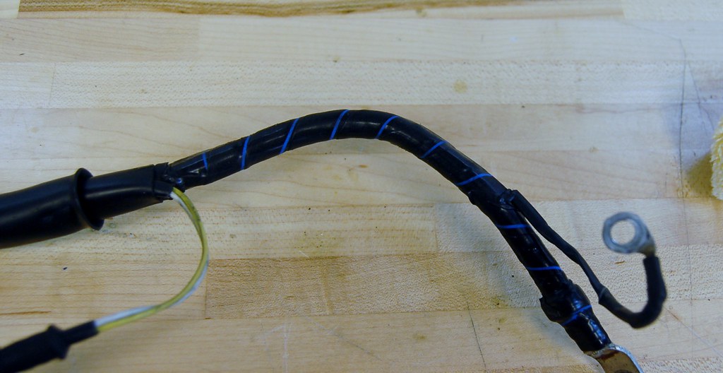
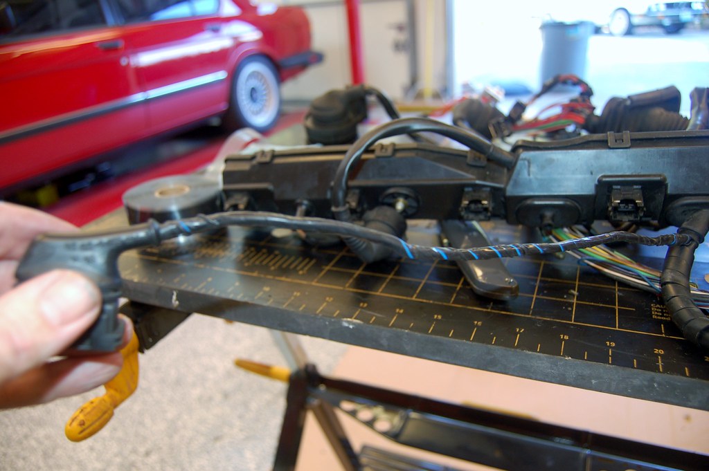
As I was working I noticed one connector was broken. The 735i harness had a good one on it, so I snipped it off and spliced it in.
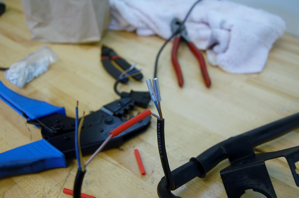
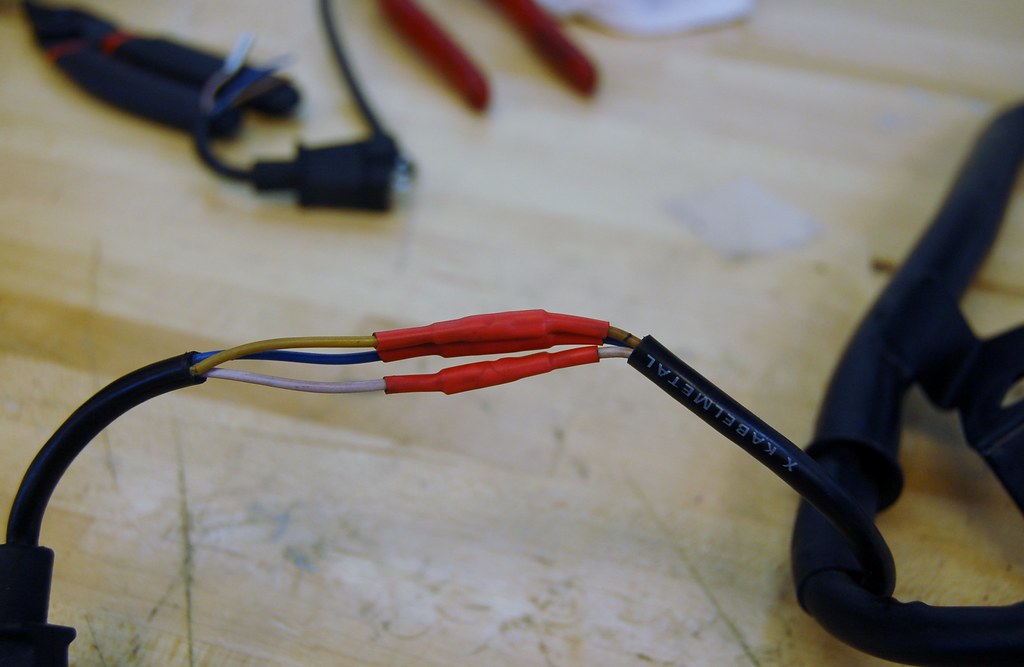
I'm also carefully cleaning all grime off the connectors and stuff so that it's like new. Still lots to do.
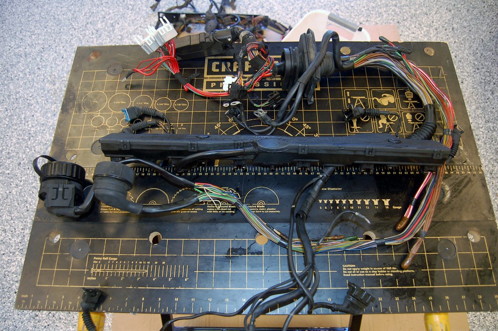
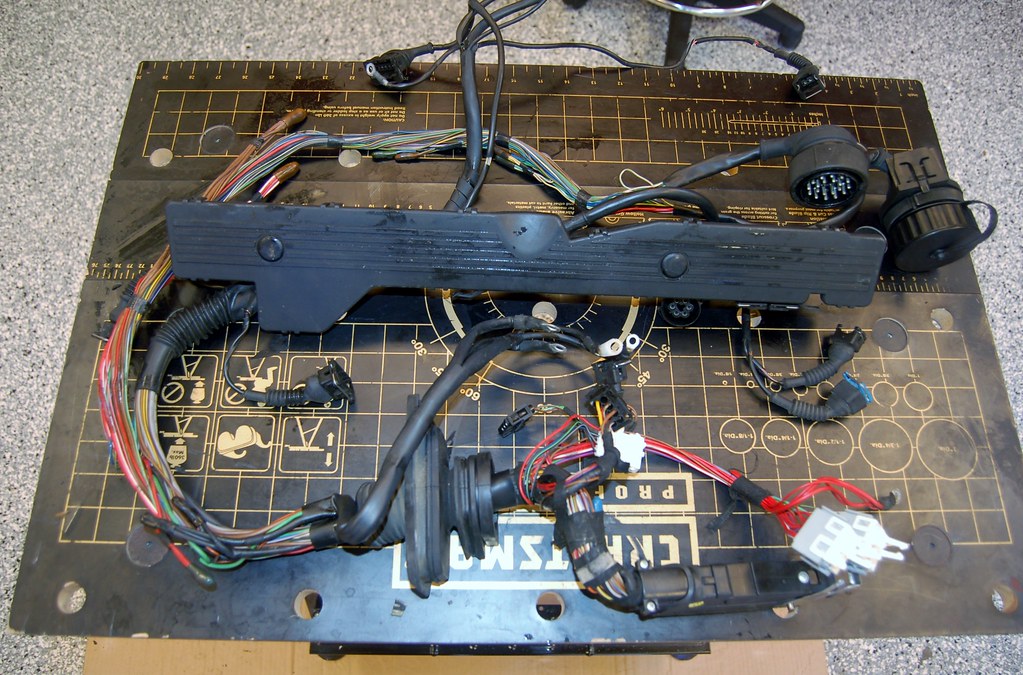
I have two. One that came from the donor 735i and another that I purchased from a member here that came from an E34. The E34 harness is in much better shape so that's what I'm basing on.
However, even it has old, hard wire insulation that cracks when bent. Today I set about removing all of that and re-wrapping using F4 tape. I've never used F4 tape before, but it seems like pretty awesome stuff!


As I was working I noticed one connector was broken. The 735i harness had a good one on it, so I snipped it off and spliced it in.


I'm also carefully cleaning all grime off the connectors and stuff so that it's like new. Still lots to do.


I finished fixing up the insulation on all the small leads on the harness.
I started re-wrapping the part of the loom that goes to the 20X connector and then realized that I wasn't sure how the harness would fit in the car.
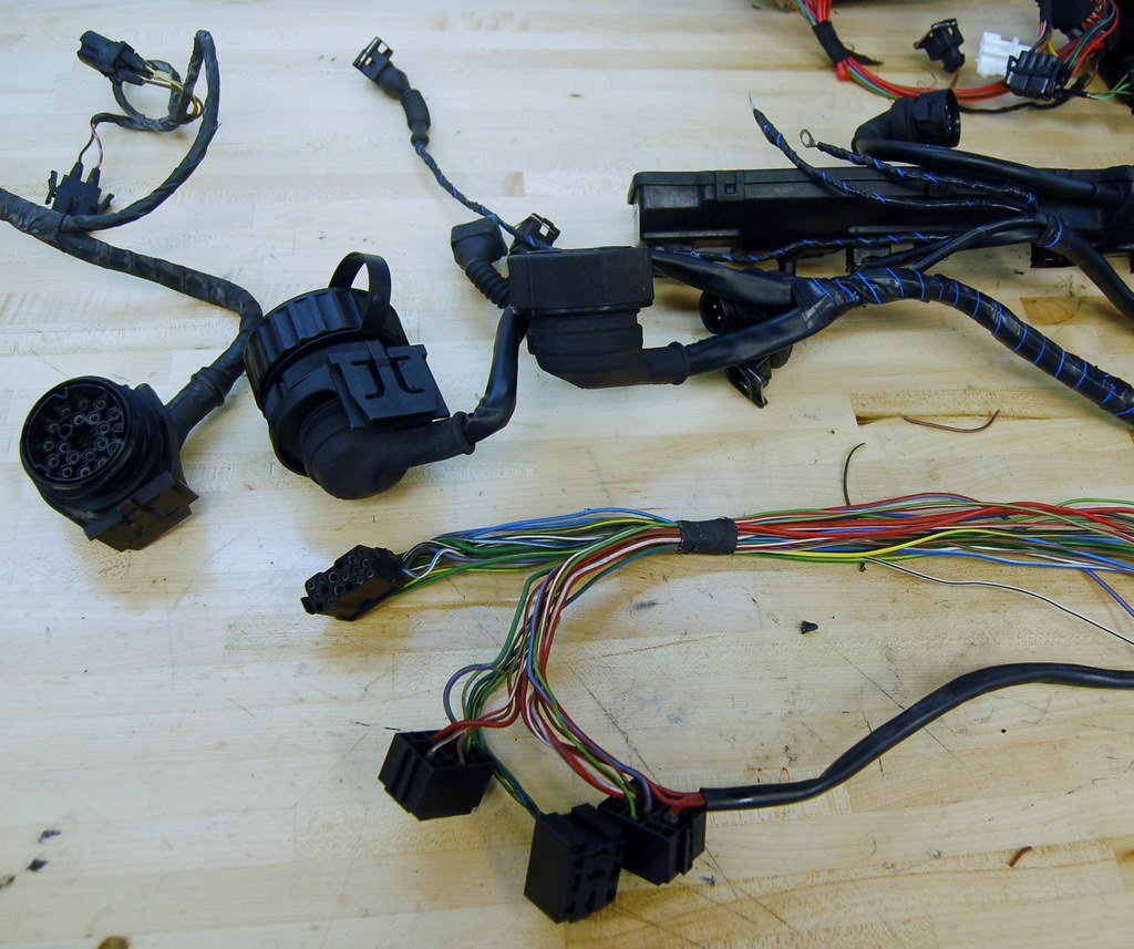
My original plan was to keep the 20X from the E34. I kept the female 20X plug from the donor, along with a nice long pigtail. My plan was to splice in a spare E28 C101 connector.
I stopped and re-read the M30B35 FAQ and saw that savannah996 went down this same path and then changed his mind, instead snipping off the 20X from the E34 harness and splicing it directly into the C101 pig-tail. I will probably do the same thing.
So now I'm going to pause on working on the harness until the motor is in the car... I don't want to do it twice. But the harness is essentially ready to go.
I started re-wrapping the part of the loom that goes to the 20X connector and then realized that I wasn't sure how the harness would fit in the car.

My original plan was to keep the 20X from the E34. I kept the female 20X plug from the donor, along with a nice long pigtail. My plan was to splice in a spare E28 C101 connector.
I stopped and re-read the M30B35 FAQ and saw that savannah996 went down this same path and then changed his mind, instead snipping off the 20X from the E34 harness and splicing it directly into the C101 pig-tail. I will probably do the same thing.
So now I'm going to pause on working on the harness until the motor is in the car... I don't want to do it twice. But the harness is essentially ready to go.
The diesel did the trick. Enough soaked into the gasket to soften it up just enough so I could get to work with a razor blade and gasket scraper.
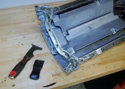
Now I'm going to soak it some more so I don't have to use the scraper to get the final bits off; I want to avoid marring the surface as much as possible.
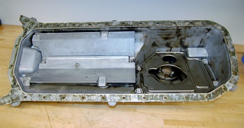
Last time I did this I was on my back under my FJ40. THAT was a bitch. I do not like oil pan gaskets.
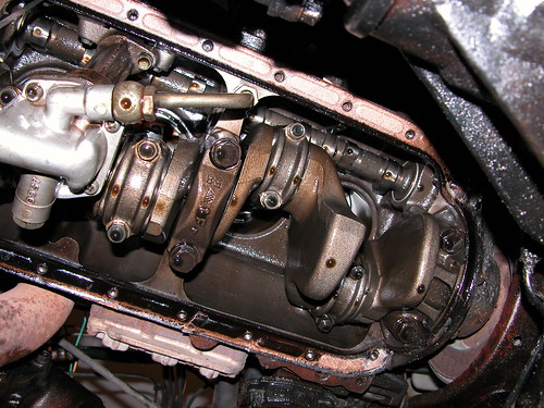

Now I'm going to soak it some more so I don't have to use the scraper to get the final bits off; I want to avoid marring the surface as much as possible.

Last time I did this I was on my back under my FJ40. THAT was a bitch. I do not like oil pan gaskets.

This is probably excruciatingly boring for most of you, but for me? Ha!
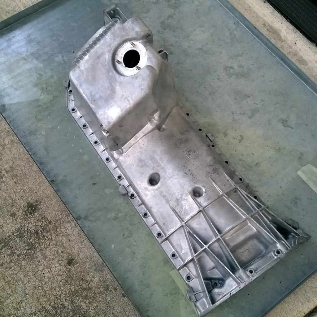
Got the oil pan as clean as it's going to be. There's still a little bit of caked on oil inside, but without putting the thing in an industrial dishwasher or something I'm calling it good enough.
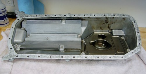
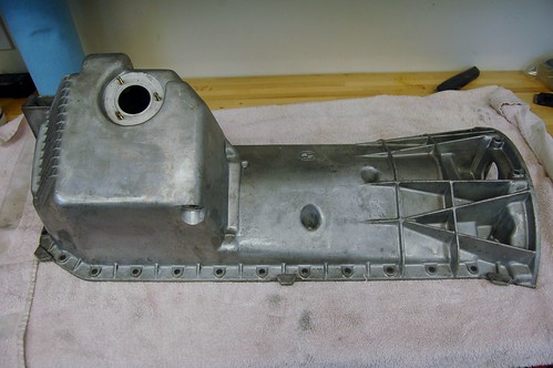
And I have officially bolted something back together on this baby!


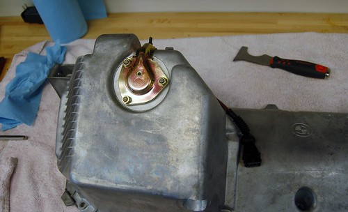
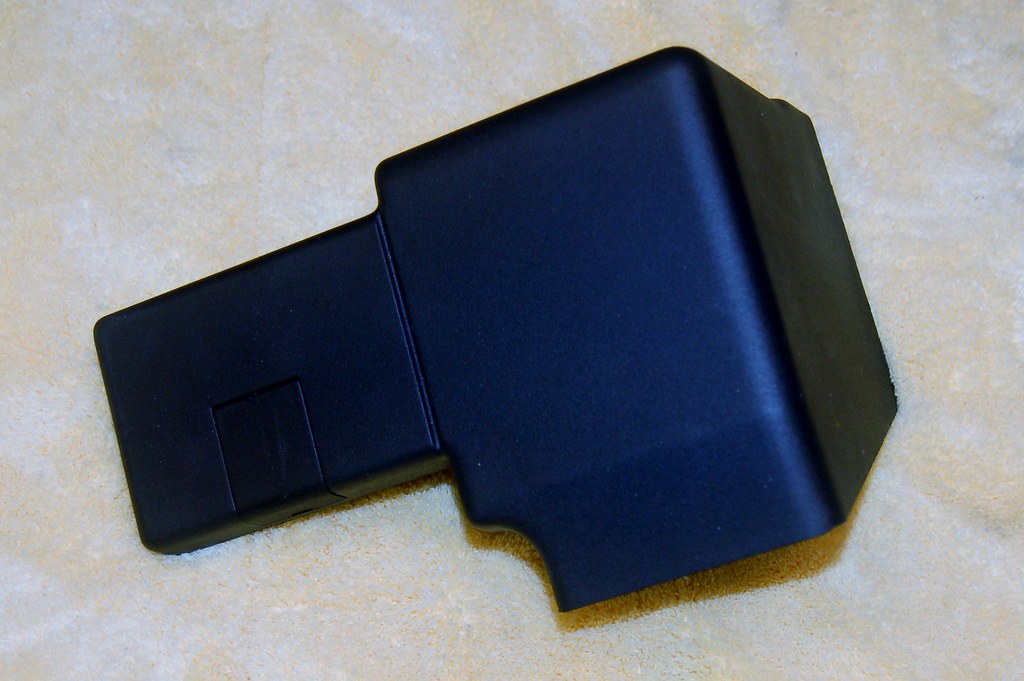
Of course I'm already missing a part. I can't find the plastic cover that goes over the hole on the back of the oil pan, part # 11131713202. Sigh.
Got the oil pan as clean as it's going to be. There's still a little bit of caked on oil inside, but without putting the thing in an industrial dishwasher or something I'm calling it good enough.


And I have officially bolted something back together on this baby!

Of course I'm already missing a part. I can't find the plastic cover that goes over the hole on the back of the oil pan, part # 11131713202. Sigh.
Got the oil pump (that I tore apart and rebuilt way back) on. Missing the clip that holds the plunger in (it's broken and I failed to order one back when I disassembled) so I can't put the oil pan on yet.
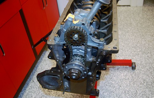
Flipped her over to start on the top. Not going to put the head on tonight 'cause I gotta go to the Sounders match. But a question:
Do I need to do any prep to the surface before putting the head gasket on (like make sure it's clean of oil or anything)?
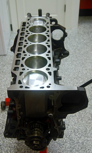

Flipped her over to start on the top. Not going to put the head on tonight 'cause I gotta go to the Sounders match. But a question:
Do I need to do any prep to the surface before putting the head gasket on (like make sure it's clean of oil or anything)?

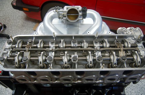
Looking at the head and trying to figure out if all is OK.
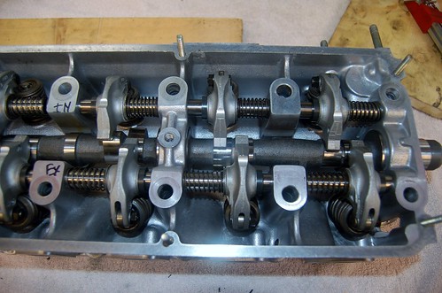
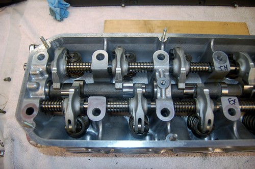
As you can see the rockers are not centered on the cams.
And on the rear on the intake side, the rocker shaft is pushed out the back of the block.
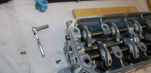
The cover will only push it in the length it is sticking out. To push it in the rest of the way, in order to make the rockers to actually be on the cams requires it to be sunk in about 3mm.
Here I'm using a socket to press it in as far as it will go:
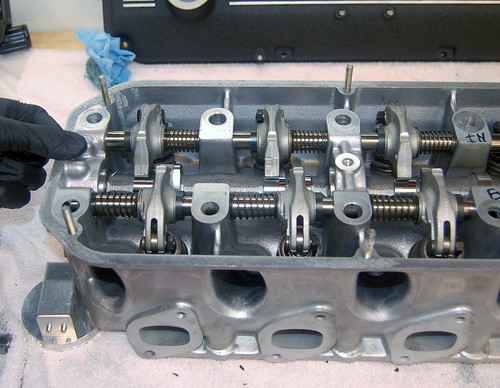
Two questions:
1) Is it a problem that the camshaft appears to be a bit too far forward and that the rockers are not centered in the cams? I can't see how the camshaft moves/doesn't move forward/back.
2) What is supposed to keep the rear intake rocker shaft pressed in sufficiently? The parts diagrams don't show any insert or thing that goes between it and the rear cover.


As you can see the rockers are not centered on the cams.
And on the rear on the intake side, the rocker shaft is pushed out the back of the block.

The cover will only push it in the length it is sticking out. To push it in the rest of the way, in order to make the rockers to actually be on the cams requires it to be sunk in about 3mm.
Here I'm using a socket to press it in as far as it will go:

Two questions:
1) Is it a problem that the camshaft appears to be a bit too far forward and that the rockers are not centered in the cams? I can't see how the camshaft moves/doesn't move forward/back.
2) What is supposed to keep the rear intake rocker shaft pressed in sufficiently? The parts diagrams don't show any insert or thing that goes between it and the rear cover.
Next problem: When I recycled the old head bolts I didn't realize the new ones didn't come with washers. So now I need to get washers.
Still not convinced the head bolts will move the rocker shafts enough to cause the rockers to align on the cams though.
Part of the problem is the camshaft is currently at a point (which I think is TDC) such that the spring vavles for #2/#3 are under max tension making it impossible to slide that rocker shaft horizontally. I can't turn the camshaft because I don't want the other valves to contact the pistons. Not sure how do to this part.
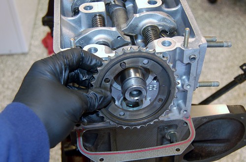
I also can't find the flange that the upper timing chain sprocket connects to. I think it must have been left at my machinists. I have another on the other B34 head, but I'll see if my machinist has it first.
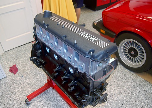
For funzies, we set the valve cover on

Still not convinced the head bolts will move the rocker shafts enough to cause the rockers to align on the cams though.
Part of the problem is the camshaft is currently at a point (which I think is TDC) such that the spring vavles for #2/#3 are under max tension making it impossible to slide that rocker shaft horizontally. I can't turn the camshaft because I don't want the other valves to contact the pistons. Not sure how do to this part.
I also can't find the flange that the upper timing chain sprocket connects to. I think it must have been left at my machinists. I have another on the other B34 head, but I'll see if my machinist has it first.

For funzies, we set the valve cover on

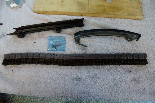
Just making sure new timing chain is the right length. New guide.
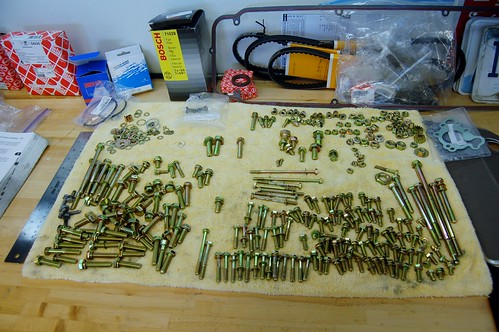
Getting the fasteners organized. You'll recall that I took pictures of each 'set' with their labeled zip locks before I sent them off to plating. Organizing like this is step one to ensuring I use the right fastener in the right place.
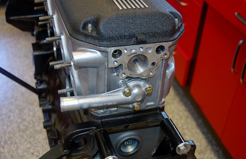
New B34 gooseneck for back of head coolant exit. The B35 has this covered up. The gooseneck off of the donor B34 was corroded through.
I'm mostly stalled at this point until I get washers for my head bolts and get a better understanding of how the rocker shafts/camshaft are supposed to line up... Also missing that sprocket flange...
I'll keep poking away at things that can be assembled regardless...

Getting the fasteners organized. You'll recall that I took pictures of each 'set' with their labeled zip locks before I sent them off to plating. Organizing like this is step one to ensuring I use the right fastener in the right place.

New B34 gooseneck for back of head coolant exit. The B35 has this covered up. The gooseneck off of the donor B34 was corroded through.

I'm mostly stalled at this point until I get washers for my head bolts and get a better understanding of how the rocker shafts/camshaft are supposed to line up... Also missing that sprocket flange...
I'll keep poking away at things that can be assembled regardless...
I just realized what happened to the timing chain sprocket flange. When I had my original B35 camshaft reground I never removed the nut, flange, and guide plate.
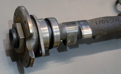
Then, I sold it.
Oops.
I guess it's a good thing I didn't sell this other B34 head I have with those parts on it :-)
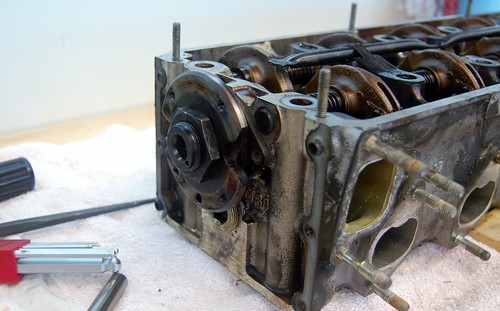
Now to figure out how to get that nut off...

Then, I sold it.
Oops.
I guess it's a good thing I didn't sell this other B34 head I have with those parts on it :-)

Now to figure out how to get that nut off...
No way to get that nut off a camshaft while it's in the head, as far as I could see.
So we used this as an excuse to actually tear down a head. Remember I used my checkbook to have the B35 head rebuilt so I never tore a head down.
Following Bentley's we used screw drivers to leverage the rockers to free them from the cam lobes and with some finagling were able to pull the camshaft out.
According to what Spencer heard when he bought the parts car this B34 came from (same car, BTW that Vlad's IE/Bav auto exhaust came from) this B34 cam is 'tuned'. I have no way of measuring that or telling but it does look to be in fine shape. Happy to sell it to someone.
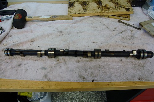
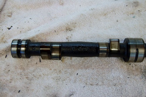
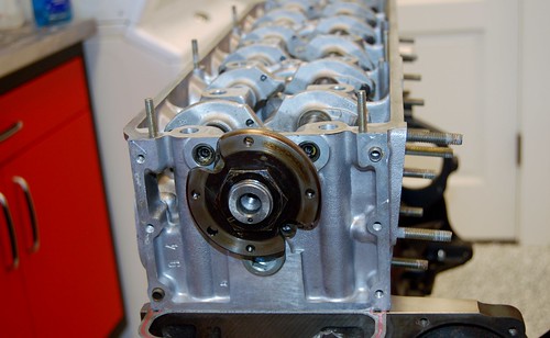
But that is neither her nor there for this project. The key is we now have the sprocket flange, etc on and in all our dinking around with this I've answered all the questions I had about how the camshaft and rocker shafts are aligned.

I have a bunch of misc parts to acquire before more progress can be made:
1 of 11131713202 (Covering Cap for oil pan)
1 of 07119934619 (lock ring for oil pump piston)
1 of 11421730294 (gasket for oil filter housing to B34 block)
14 of 11120621145 (washers for head bolts)
4 of 11421252343 (crush washers for banjo bolts)
The biggest blocker is the washers for the head bolts. Are there anything special about these washers?
So we used this as an excuse to actually tear down a head. Remember I used my checkbook to have the B35 head rebuilt so I never tore a head down.
Following Bentley's we used screw drivers to leverage the rockers to free them from the cam lobes and with some finagling were able to pull the camshaft out.
According to what Spencer heard when he bought the parts car this B34 came from (same car, BTW that Vlad's IE/Bav auto exhaust came from) this B34 cam is 'tuned'. I have no way of measuring that or telling but it does look to be in fine shape. Happy to sell it to someone.


But that is neither her nor there for this project. The key is we now have the sprocket flange, etc on and in all our dinking around with this I've answered all the questions I had about how the camshaft and rocker shafts are aligned.

I have a bunch of misc parts to acquire before more progress can be made:
1 of 11131713202 (Covering Cap for oil pan)
1 of 07119934619 (lock ring for oil pump piston)
1 of 11421730294 (gasket for oil filter housing to B34 block)
14 of 11120621145 (washers for head bolts)
4 of 11421252343 (crush washers for banjo bolts)
The biggest blocker is the washers for the head bolts. Are there anything special about these washers?
Restating: The rocker shafts have notches in them and the head bolts have flanges at the top that fit into these. This is what keeps the rocker shafts from moving laterally.cek wrote:Ok, it took just a few more minutes of me & my son thinking about it and we figured #1 out. The rocker shafts are held in place horizontally by the head bolts.
Would someone please verify that this is correct and comment.
I know that on some other engines there are either clips or a plate that keep the rocker shafts from moving laterally. I have poured over the parts diagrams and Bentley and think we're right about this, but I just want to make sure I'm not missing something.
Also, I'd love it if any of you who've been through this before would comment with "watch out for" or "the mistake I made" or "don't forget to". Before I clamp the head down and install the timing chain, etc...
Thanks.
-
Kyle in NO
- Posts: 17638
- Joined: Feb 12, 2006 12:00 PM
- Location: Nasty Orleans------> Batten-Rooehjch------>More Souther LA
Another noob question:
EDIT: Never mind. I read this:
http://www.mye28.com/viewtopic.php?t=70052
Where is it [critical | optional | not advised] to use locktite?
E.g. On these bolts that hold the camshaft chain sprocket?
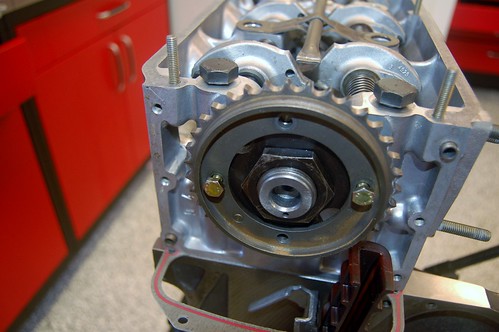
EDIT: Never mind. I read this:
http://www.mye28.com/viewtopic.php?t=70052
Where is it [critical | optional | not advised] to use locktite?
E.g. On these bolts that hold the camshaft chain sprocket?

Progress...
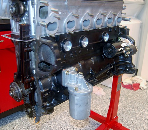
Bolted on some baubles like the oil filter housing.
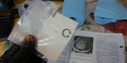
Got a clip for the oil pump.
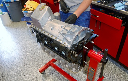
After CJ & I bolted down the head we did the oil pan.
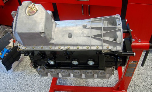
Sexy, I know.
Found that I have either lost or never ordered timing chain cover gaskets. Oops.
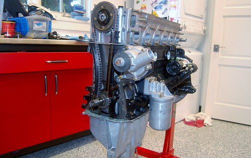
Test fit the intake manifold. It's starting to look like a real engine...
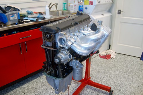
I'm now considering powder coating the throttle body. Should I?
Bolted on some baubles like the oil filter housing.

Got a clip for the oil pump.

After CJ & I bolted down the head we did the oil pan.


Sexy, I know.
Found that I have either lost or never ordered timing chain cover gaskets. Oops.

Test fit the intake manifold. It's starting to look like a real engine...

I'm now considering powder coating the throttle body. Should I?
Working on clubbing baby seals, er, I mean replacing seals.
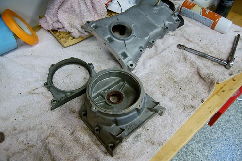
Like most questions I ask in this thread, I figure I'm not going to get any answers. Sometimes I wonder if people are actually reading this. Or maybe no one likes me.
Anyway, I've read that it's recommended that when putting on seals you should mount them at different locations than before within the part holding the seal, so that they ride on a different spot on the rotating part.
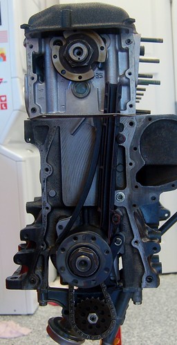
Then I look at the back of my crankshaft and notice this has a channel on it. And I wonder "What is THAT for?"
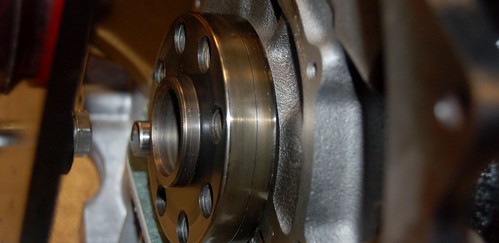
So there's my question. What is THAT for?

Like most questions I ask in this thread, I figure I'm not going to get any answers. Sometimes I wonder if people are actually reading this. Or maybe no one likes me.
Anyway, I've read that it's recommended that when putting on seals you should mount them at different locations than before within the part holding the seal, so that they ride on a different spot on the rotating part.
Then I look at the back of my crankshaft and notice this has a channel on it. And I wonder "What is THAT for?"

So there's my question. What is THAT for?
-
Coldswede
- Posts: 6859
- Joined: Oct 10, 2008 1:48 PM
- Location: Back U.P. North,. Where the water's blue, the wind is free and seasons four.
I think "That" might be the reason you install the seals a slightly different depth. The seal actually wears a low spot in the journal and can cause a leak.
I have seen grooves machined into journals and was told it helps throw off excess oil at high rpm again preventing leaks.
Not sure which of the two I am looking at in the picture.
We do, I do anyway, read your posts
I have seen grooves machined into journals and was told it helps throw off excess oil at high rpm again preventing leaks.
Not sure which of the two I am looking at in the picture.
We do, I do anyway, read your posts
-
athayer187
- Posts: 1623
- Joined: May 10, 2006 11:27 AM
- Location: Cheshire, CT


