Beginnings of simulator: Materials ordered for FFB Wheel

Post your photos and videos here!
Post Reply
Xenocide
Posts: 3370
Joined: Jun 08, 2008 4:29 PM
Location: Atlanta, GA

Beginnings of simulator: Materials ordered for FFB Wheel

Post by Xenocide »

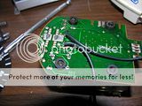
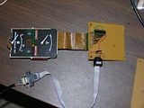
Well, I sourced a spare cluster from the yard and finally had time to start tearing into it. I decided not to try to drive it as the car would have. I figured it'd be easier to isolate all of the lights and needle motors and drive them independently with a PIC. I just finished running cables for the speedometer needle and the tachometer needle.
Image
This shows the solder points to drive the speedo needle. I scraped away the traces around it to isolate it from the previous circuit. It may or may not have made a difference, but the cluster was roached anyway, so no need to take the chance.
Image
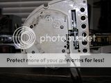
I put a strain relief in the wires I ran, just in case.

Image
There were two un-used holes in the back which served as perfect spots for the cables to exit.

Image
After testing, it appears that the needle is driven by a 0-5 volt input. I haven't yet plotted data points to check, but I assume it's a logarithmic decay.

As for the tachometer, it's a 4 pin stepper motor, but I tried all the different stepper motor configurations I know of, and none of them seemed to work. I'll have to take a closer look at it later.
Last edited by Xenocide on Nov 01, 2011 5:03 PM, edited 2 times in total.
Eta power
Posts: 1413
Joined: Mar 25, 2010 10:33 PM
Location: Vancouver, WA

Post by Eta power »

Awesome! :banana: Can't wait to see more!
Xenocide
Posts: 3370
Joined: Jun 08, 2008 4:29 PM
Location: Atlanta, GA

Post by Xenocide »

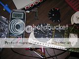
I scored a new tach at the yard today. An e28 came on the lot about a week ago and I'd been meaning to check it out. I finally did today and sure enough, I found a cluster missing the casing and speedo, but with the 7k tach and plate intact. The old style cluster is MUCH easier to deal with, no stepper motors, just an ordinary 0-5 volt DC input. I'm thinking that the stepper motors were probably more stable in rough or bumpy conditions, which is why BMW switched, but this will be perfect for my needs.
Image
This is the motor for the tach needle, really nothing to it, huge solder points and everything :)

Image
The cluster all buttoned up. So far I've only hooked up the tach and speedo, but I'll hopefully be hooking up the temp, fuel, and possibly blinkers and SI lights (they won't work, but at least they'll be lit).

http://www.youtube.com/watch?v=xbJHGj-17V8
The tach and speedo only pull about 20 mA each, so they can both very safely be driven by the Arduino. They aren't tied together using any real gear ratio or anything, it's just for effect. I did this partially because I had some code ready to go with only minor modifications, partially because I'm a very childish person and I really wanted to see that tachometer needle bounce on a down shift. :haul:
Xenocide
Posts: 3370
Joined: Jun 08, 2008 4:29 PM
Location: Atlanta, GA

Post by Xenocide »

Progress has inched along, I've finally gotten the software set up. Unfortunately I'm out of filter capacitors for the PIC18F oscillator circuit and the internal oscillator isn't accurate enough for a serial connection, so I'm using an arduino, but hell, it works :D

I've got an H-pattern shifter prototype built and a solid design for a force feedback wheel using an e30 steering column and wheel, hopefully over the next few weeks I'll finish putting the pedal box together and get the H-bridge for the steering wheel motor running.

http://www.youtube.com/watch?v=2QjfCc3j ... er&list=UL
mooseheadm5
Beamter
Beamter
Posts: 23035
Joined: Apr 08, 2009 10:30 PM
Location: Charlottesville, VA
Contact:

Post by mooseheadm5 »

Let me know if you need any more parts. I have a couple of E30s to cut up.
Xenocide
Posts: 3370
Joined: Jun 08, 2008 4:29 PM
Location: Atlanta, GA

Post by Xenocide »

mooseheadm5 wrote:Let me know if you need any more parts. I have a couple of E30s to cut up.
Will do Paul, thanks for the offer!

I think the main thing I need now is time (and an extra brain to figure out the PID control loop for the force feedback ;) ).
Xenocide
Posts: 3370
Joined: Jun 08, 2008 4:29 PM
Location: Atlanta, GA

Post by Xenocide »

Image

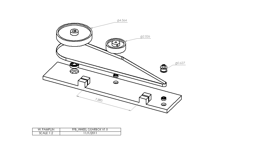
Well, I just placed the orders with SDP-SI and McMaster Carr. The force feedback wheel should become a reality inside the next few weeks. :D

The pic above is a Solidworks rendering of it. I built the models of the gears based on dimensions from the SDP-SI catalogs. They are actually 0.200" pitch (XL) timing belt gears, I just didn't model the teeth. Also missing from the rendering are the shafts, top plate (and bearings), and the wiper motor to power the whole thing.

The small gear on the right is a 10 tooth for the input shaft (from the steering column), the middle gear is a 40 tooth for the potentiometer to measure position, and the far left gear is a 72 tooth for the windshield wiper motor to mount to. The small blocks at the bottom of the plate are stops for a clamp which will mount to the belt. When the clamp hits the blocks, it will stop the whole system from rotating. If I did the math right it should facilitate 3 turns from lock to lock. The 4:1 reduction to the potentiometer gear allows for 270° of rotation, so that I can use most commonly available pots. The last gear is at a huge 7.2:1 reduction to counteract some of the gearing on the wiper motor. This will mean that the wiper motor will only turn ~180°, which is just fine. It's more for delivering vibrations, impacts, and steering feel, so resolution isn't terribly important. The main thing I want to convey through the wheel is that threshold of grip just before catastrophic understeer takes over. I will be implementing a weak, speed-dependent centering algorithm.

The plate itself will be made from 1/2" thick high density polyethylene, as are the blocks.

Soon to come: the I/O board and the H-Bridge :D

This thing should beat the hell out of any off the shelf racing wheel (and cost less to boot) :banana:
neilandbob
Posts: 21
Joined: Dec 15, 2010 4:31 PM
Location: Sheffield, UK

Post by neilandbob »

Insane, it took me a while to work out what you're doing, can't wait to see it finished.
CoyoteStarfish
Posts: 1016
Joined: Nov 14, 2008 6:06 PM
Location: Miami, FL

Post by CoyoteStarfish »

This is nuts. Nice work man.

This almost makes me want a cheezy gauge-sweep when I start up my car now.
Das_Prachtstrasse
Posts: 5616
Joined: Sep 10, 2006 7:06 AM
Location: Melbourne, Doooown Under

Post by Das_Prachtstrasse »

Haven't checked the videos yet, but this is supremely cool. I want one for LFS!
Xenocide
Posts: 3370
Joined: Jun 08, 2008 4:29 PM
Location: Atlanta, GA

Post by Xenocide »

http://youtu.be/vwM9KomI6ww

While I have been waiting for the parts to show up I had some time to play around with solidworks, and particularly the exploded view feature. It's really a great program, it has saved me hours of work and countless $$$.

I've got some cool stuff going together on the electronics side of things, unfortunately I haven't had a chance to take pictures yet though. I've got the PIC18F4550 interfacing to x-sim via 9600 baud serial. The PIC receives game data (speed, tire/water/oil temp, RPM, gear, fuel level, etc.) from x-sim and displays it using a rudimentary menu system on a 16x2 LCD. Right now I've got only got 2 PWM outputs connected, driving the tachometer and speedometer. I have code set up so that it can drive up to 8 total PWM outputs, which can pretty easily be expanded later if need be. I'll just have to build amplifier circuits for them because the gauges pull 60~80mA each, which is too much for the PIC to handle on its own. Also I'll be building a high power H-bridge (70 volts at ~90 amps max, closer to 12v @ 10 amps in operation) to drive the steering wheel's wiper motor.

So far I've got roughly $150 into the project, including the cost of an e30 steering column and pedal box (junkyard), the HDPE from McMaster-Carr, gears from SDP-SI, and various electric components from assorted sources. I think the final cost should come out to around $200, about the same as an average off the shelf FFB steering wheel.
Xenocide
Posts: 3370
Joined: Jun 08, 2008 4:29 PM
Location: Atlanta, GA

Post by Xenocide »

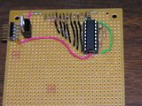
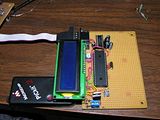
My Tayda electronics order finally came in! I got the shift light circuit built on a separate daughterboard:
Image
It connects to the SI section of the cluster through the stock connector as shown
Image

It actually fits right where the original SI board went :D

I haven't yet added the amplifier circuits to drive the gauges, hopefully I can get to that today. The sequential shift light is set up so that I'll set two threshold RPM values (probably 6500 and 7000 or so). The first green light will illuminate at the lower limit, and it will light up more and more lights until it reaches the ideal shift point (the upper limit). I can't wait to get the rest of this board designed so that I can try it out in game :banana:

I also have been meaning to post a pic of the motherboard:
Image

It's far from complete, but it's a good start. So far it's just the PIC18F4550 processor and a MAX232 serial level converter along with the associated components to drive them. As soon as the mosfets and sockets come in, the high power H-bridge that will drive the wiper motor for the steering wheel will also be on this board.
tangerineman91
Posts: 362
Joined: Mar 28, 2010 1:38 AM
Location: Chattanooga, TN

Post by tangerineman91 »

This is awesome.
Cooperman
Posts: 902
Joined: Apr 17, 2009 11:21 PM
Location: Fayetteville, AR

Post by Cooperman »

Kudos to you. Awesome work.
Das_Prachtstrasse
Posts: 5616
Joined: Sep 10, 2006 7:06 AM
Location: Melbourne, Doooown Under

Post by Das_Prachtstrasse »

I want one.
tig
Posts: 9311
Joined: Mar 18, 2013 6:25 PM
Location: Durango
Contact:

Re: Beginnings of simulator: Materials ordered for FFB Wheel

Post by tig »

Bump for just plain awesome.
ericmike
Posts: 46
Joined: Feb 12, 2015 9:37 PM
Location: Raeford, NC

Re: Beginnings of simulator: Materials ordered for FFB Wheel

Post by ericmike »

i agree
Xenocide
Posts: 3370
Joined: Jun 08, 2008 4:29 PM
Location: Atlanta, GA

Re: Beginnings of simulator: Materials ordered for FFB Wheel

Post by Xenocide »

I can't tell you how many times I've ALMOST worked on this one.

Since that last post I've gradgieated, taken a big-boy(ish) job, got married, bought a house, garaged the e28, and been driving the road slug W123. I gotta mention, there's a huge push from the wifey to get rid of it after I pinched the oil canister o-ring and it shit oil all over the side of the house.
Diesel oil on latex paint bad. Brake clean good. Acetone strips that paint REALLY effectively. Strong purple power WILL kill just about all of your plants (if the oil didn't already). I learned a lot last week.

I now have a cheap and dirty router at home and have access to a pretty good but small tormach. The design needs to be updated for mounting and stuff. I have an e30 steering column, but need to shorten it and mount it. Probably most of the electronics design will be redone because circuit boards are cheap and it would probably coincide with the OBC project (will be driving the cluster, maybe).

My boss has been trying to convince me to buy old robits for their motors to use for the motion platform. I think we can probably do better with AC induction motors and clever drivers.
Post Reply