Auto TPS to Manual TPS Conversion Questions

E28 technical advice asked and given! Troubleshooting, modifications and more.
Post Reply
vinceg101
Posts: 4894
Joined: Jun 20, 2007 2:40 AM
Location: Los Angeles, CA

Auto TPS to Manual TPS Conversion Questions

Post by vinceg101 »

So in the middle of trying to complete my Front End & Engine Overhaul for the M535i, one of the items was converting the existing Automatic TPS on the Throttle Body to a new Manual TPS.
This was never done when the car underwent a Transmission swap to a 5-Speed way back when.

My issue and question is how to modify the car's existing Main Wire Harness which has the Auto TPS connectors by wiring into it the Manual Connector Plug. There are some seemingly conflicting issues I am having with the information in the ETM and what I see in the car. So I an unclear on which wires to pay attention to and which to ignore/cut/abandon. Note that there is no power to this car at the moment so forget running any electronic diagnostics or metering tests.
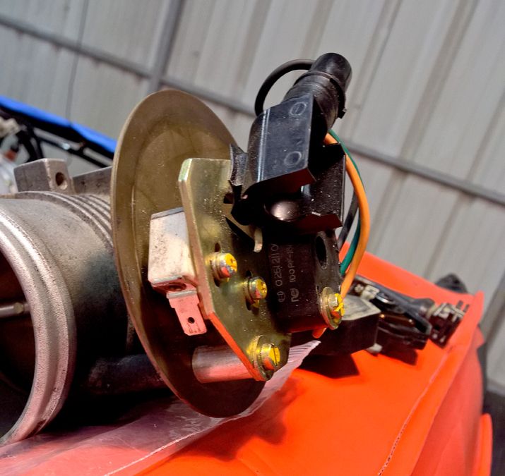
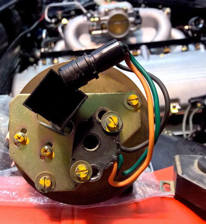
For edification, this is the what the Auto TPS looks like inside:
Image
Image

Inside this is the wiring:
(1) round barrel connector with an Orange, Green and Black wire; this connects to another barrel connector in the Harness
(1) block with two spade terminals that connector to two connectors in the Harness

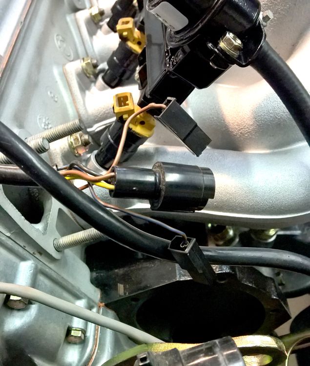
Here is the Wire Harness side:
Image

It has:
(1) round barrel connector with a Yellow, Brown, and Black wire
(1) spade terminal connector with a Brown wire
(1) spade terminal connector with a Brown/Blue wire

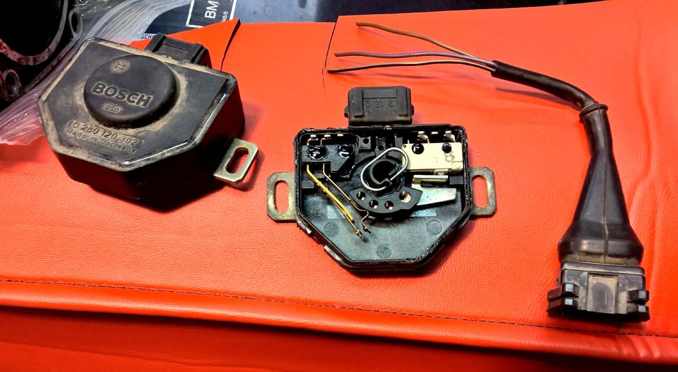
The Manual TPS looks this inside when you crack it open with the connector plug next to it that is present in a Manual Wire Harness:
Image

The wires in Connector Plug are:
(1) Brown wire
(1) Brown/Black wire
(1) Brown/Violet wire

According to the ETM, a Manual TPS is wired as follows:
(1) Brown/Blue wire for closed throttle position
(1) Brown/Black wire for open throttle position
(1) Brown ground
And an Automatic TPS is wired thus:
(1) Brown/Blue for throttle position input
(1) Brown ground

So, like I said, I am looking for information and instruction on which wires to connect to what and which to ignore. At the very least some insight into matching the wires I see in the car to the ETM.
Any and all help is very welcome.

Thanks.
demetk
Posts: 8431
Joined: Aug 09, 2007 8:58 AM
Location: CT, USA

Re: Auto TPS to Manual TPS Conversion Questions

Post by demetk »

You don't need the round connector, only the 2 rectangular connectors. But together, they will only give you idle and off idle signals, with the off idle signal simply being no signal at all. You also need an additional wire run to pin 3 of the ecu for WOT signal.

So you will connect brown/blue to brown/blue, brown to brown, and the brown/black you will run to pin 3 of the ecu.
vinceg101
Posts: 4894
Joined: Jun 20, 2007 2:40 AM
Location: Los Angeles, CA

Re: Auto TPS to Manual TPS Conversion Questions

Post by vinceg101 »

demetk wrote:You don't need the round connector, only the 2 rectangular connectors. But together, they will only give you idle and off idle signals, with the off idle signal simply being no signal at all. You also need an additional wire run to pin 3 of the ecu for WOT signal.

So you will connect brown/blue to brown/blue, brown to brown, and the brown/black you will run to pin 3 of the ecu.
Bingo, thanks for this. I would have never have guessed this.
Good thing we haven't closed up the ECU connector in the cabin yet.

Out of curiosity, what are the wires in the round connectors? Auto Trans Position Range Switch input?
demetk
Posts: 8431
Joined: Aug 09, 2007 8:58 AM
Location: CT, USA

Re: Auto TPS to Manual TPS Conversion Questions

Post by demetk »

Well the round plug along with the potentiometer plays an indirect role in providing the WOT signal to the ecu. The potentiometer's role is to provide the tranny computer with throttle position for regulating the shifting pattern. As soon as the potentiometer signal reaches a certain voltage (with sufficient throttle opening) the tranny computer sends a WOT signal via the brown/black wire to the ecu. That throttle opening should be equivalent to the 75% travel the manual TPS must travel to generate a WOT signal to the ecu.

So don't forget to disconnect the tranny computer. I would just intercept the brown/black wire from the tranny computer to the ecu and splice in at that point.
demetk
Posts: 8431
Joined: Aug 09, 2007 8:58 AM
Location: CT, USA

Re: Auto TPS to Manual TPS Conversion Questions

Post by demetk »

It's interesting to see how 2 wires can provide the 3 running states, idle, off idle and wot.

Both brown/blue and brown/black wires have a 5 volt reference voltage. So when each has voltage they can be considered to be high. When each wire is grounded with the brown wire, via the corresponding switch in the TPS, it can be considered to be low.

Here's the mapping,

brown/blue - brown/black -> state
low - high -> idle
high - high -> off idle
high - low -> wot

cheers
tn535i
Posts: 5590
Joined: Jul 14, 2006 1:30 PM
Location: Middle Tennessee

Re: Auto TPS to Manual TPS Conversion Questions

Post by tn535i »

Well actually the three wires can give 4 states to the ECM. At least I know on the S38 the low-low state which is given by a bridge plug puts the computer in open loop idle mode so you can tweak the idle mixture on the AFM and balance the T/B's.

I guess I'm not sure if it does the same on the M30. Anyone know about that? It would be usefull for tuning.
demetk
Posts: 8431
Joined: Aug 09, 2007 8:58 AM
Location: CT, USA

Re: Auto TPS to Manual TPS Conversion Questions

Post by demetk »

I haven't tested whether sending both wires to ground would do that, but that would be a useful feature on the M30.
Post Reply