My 535is Turbo Buildup Thread! - update 11/26//09
-
bmwfan1957
- Posts: 525
- Joined: Feb 12, 2006 12:00 PM
- Location: Meridian, ID
Update time! I didn't have a whole lot of time today to get much done but I knocked out a few odds and ends and took some pics.
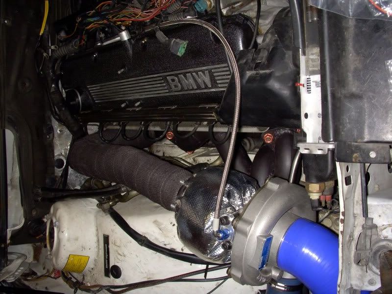
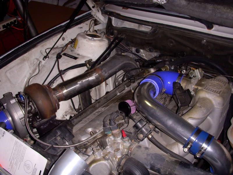
Engine bay shot
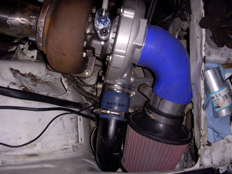
Air filter and BPV fittings. I have an upgraded billet bosch BPV replacement. (thank you Volvo)
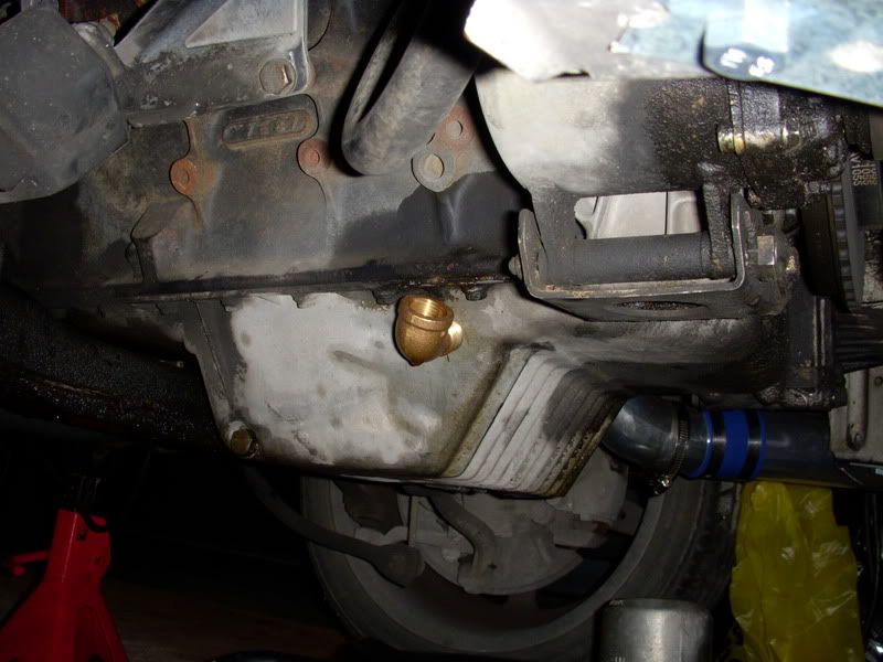
Oil return installed.
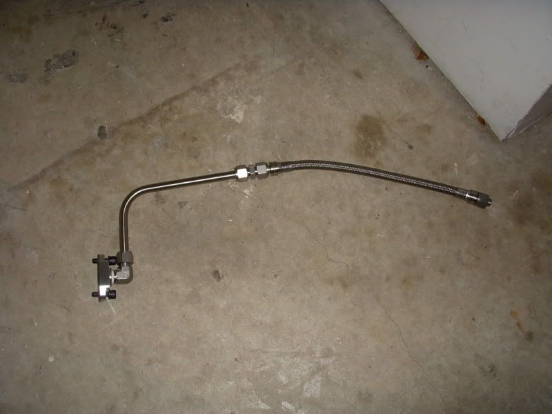
All stainless Swagelok oil return.
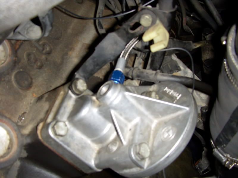
Oil feed in filter housing installed
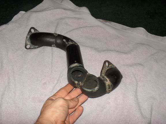
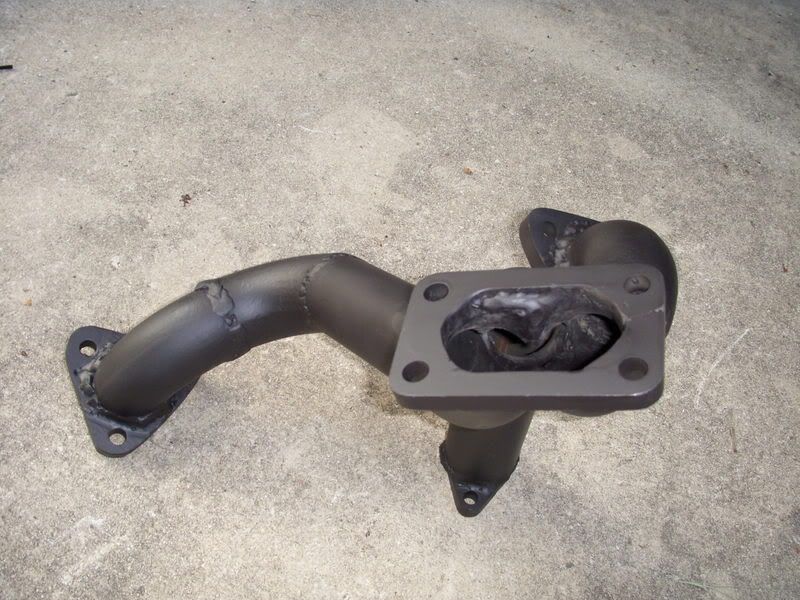
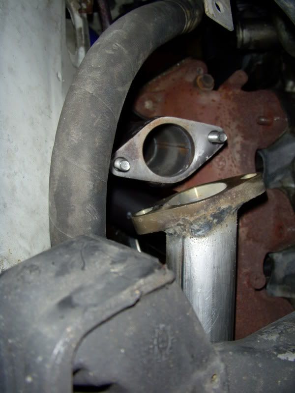
Wastegate dump pipe
I've still got lots to do. Hopefully I will get some more done tomorrow. I will take more pics as usual.
Engine bay shot

Air filter and BPV fittings. I have an upgraded billet bosch BPV replacement. (thank you Volvo)

Oil return installed.

All stainless Swagelok oil return.

Oil feed in filter housing installed

Wastegate dump pipe


I've still got lots to do. Hopefully I will get some more done tomorrow. I will take more pics as usual.
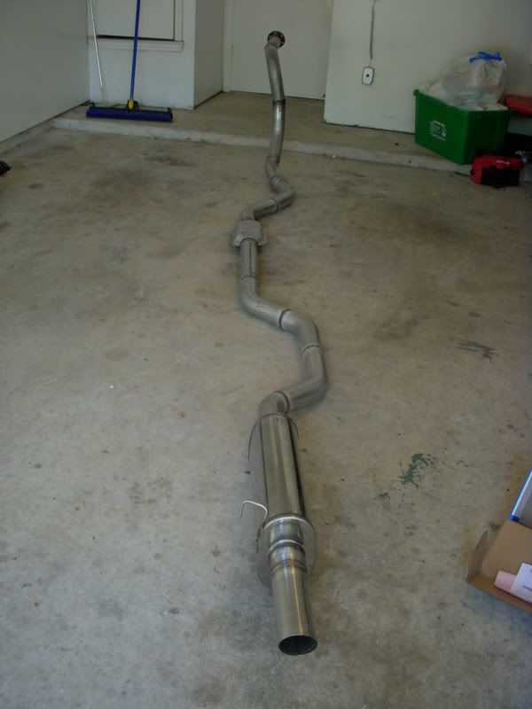
Exhaust is done! 3" Mandrel bends with a Magnaflow cat and muffler. Tip is just some cleaned up 3" SS tubing TIG'd on.
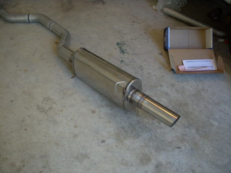
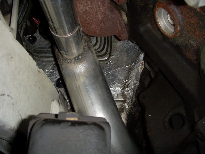
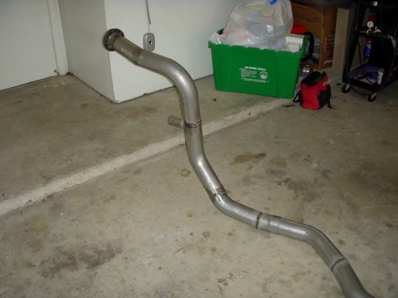
Downpipe closeup
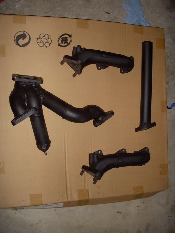
Manifolds and WG dump
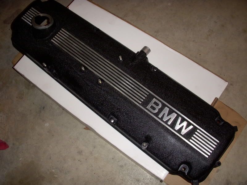
I wanted the valve cover and intake to look decent as they were orignally dirty and covered in cosmoline. I went for the not so original but clean wrinkle black with shaved raised lettering. It looks even better in person.

I should get the downpipe wrapped tomorrow so I can reinstall all of the exhooassed parts and the turbo with all new gaskets as well as get the intake and valve cover reinstalled after I do a valve adjustment.


Downpipe closeup

Manifolds and WG dump

I wanted the valve cover and intake to look decent as they were orignally dirty and covered in cosmoline. I went for the not so original but clean wrinkle black with shaved raised lettering. It looks even better in person.


I should get the downpipe wrapped tomorrow so I can reinstall all of the exhooassed parts and the turbo with all new gaskets as well as get the intake and valve cover reinstalled after I do a valve adjustment.
Well, I got more done this weekend. Had fun putting in new parts. The exhaust is installed and looks great. I've almost wrapped up everything under the hood. Only a few clamps here and there, a little wiring and some extra heat wrap on the exhaust side.
Intake and BPV installed.
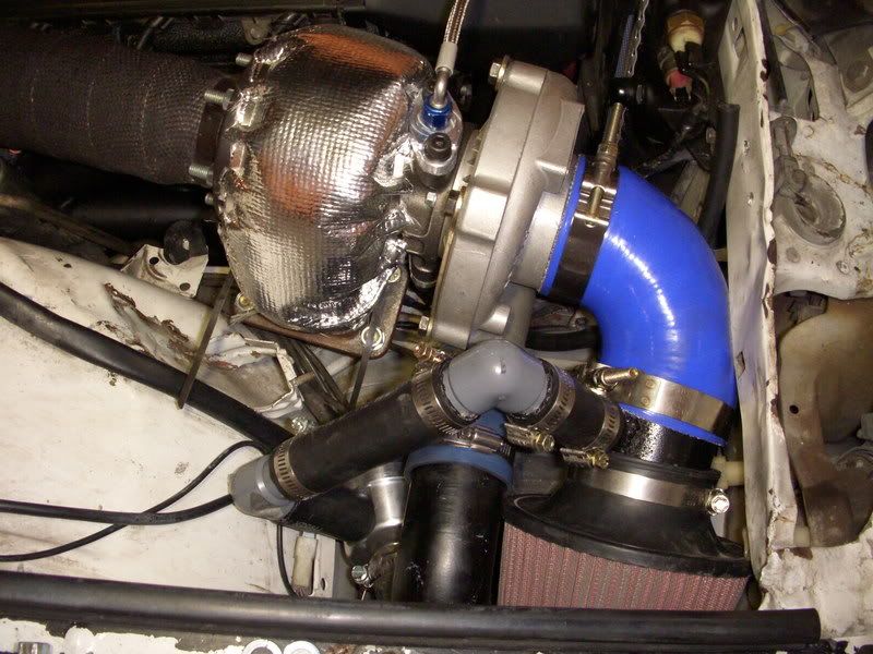
Wastegate installed. You can also see the oil return line mounted up.
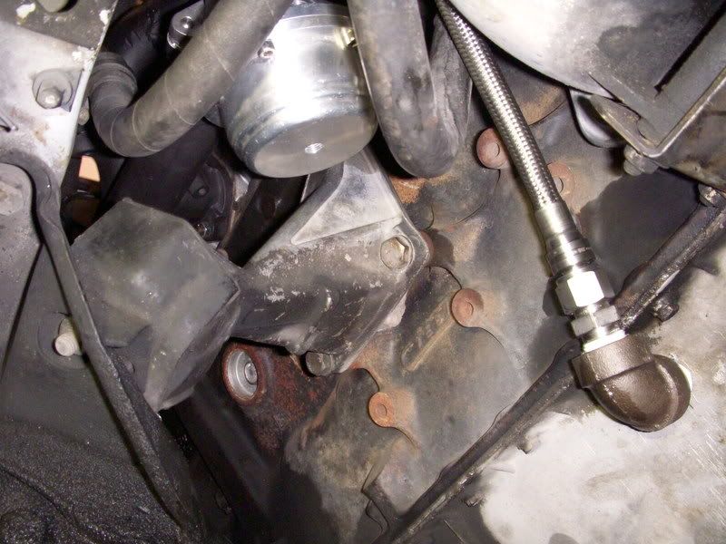
Custom catch can I made up - its baffled inside and is packed with stainless coily cleaning pads. It has a drain on the bottom. Now I just need to make a mount for it.
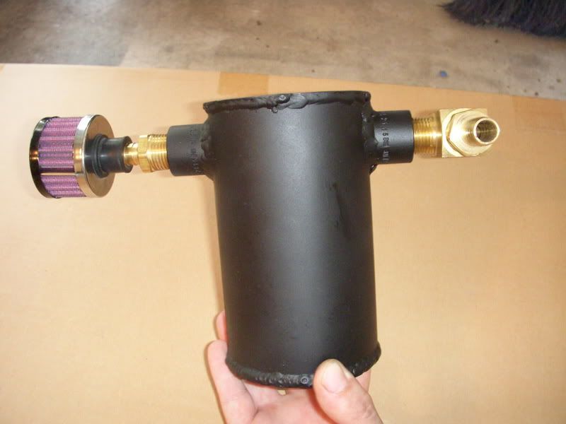
Megasquirt and my adapter box. It has the Glen's Garage idle board inside it. The pink wire is for my WB o2 input.
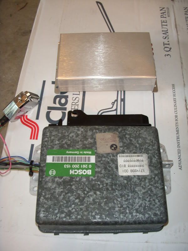
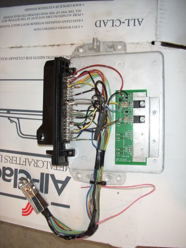
Injectors are in and all of the IC piping back on.
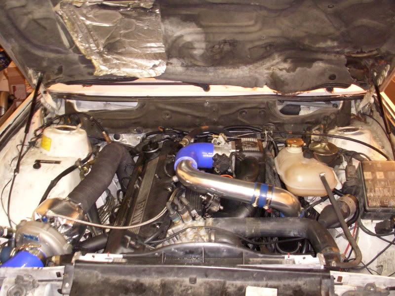
Intake and BPV installed.

Wastegate installed. You can also see the oil return line mounted up.

Custom catch can I made up - its baffled inside and is packed with stainless coily cleaning pads. It has a drain on the bottom. Now I just need to make a mount for it.

Megasquirt and my adapter box. It has the Glen's Garage idle board inside it. The pink wire is for my WB o2 input.


Injectors are in and all of the IC piping back on.

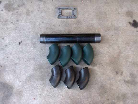
I used the same thing (pics in thread). I also thought about doing the whole brass thing, but I think they should hold up pretty good.Big Bronze Rim wrote:Ya, I want to find some in brass, but I may just wrap these in the thermal wrap I have and see how they fare.Jays535is wrote:Nice! On your BPV install are those 1" sprinkler 90* elbows?
Only the pipe and the connector were from a Volvo (740 turbo IIRC). I have a giant box of hoses, pipes, brackets and random crap I have collected over the years. I have the valve from the Volvo somewhere and it probably would have worked but it was kind of large.The BPV im using is a new billet aluminum Bosch replacement.
A few little update pics:
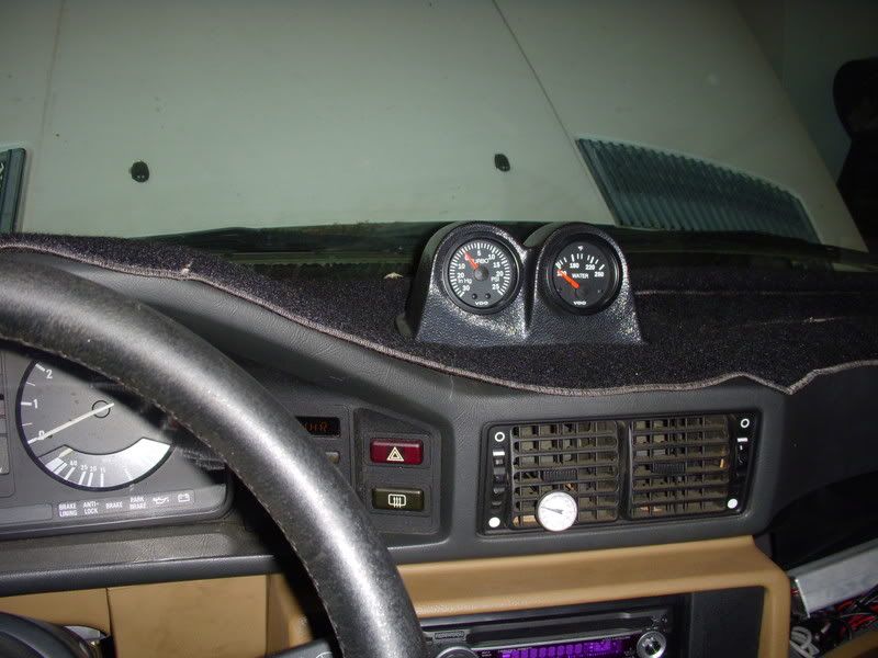
Gauge pod install. I think I am going to swap out the water temp for oil pressure, I just had the temp gauge when my stock gauge stopped working but its all good now. For now though it will work.
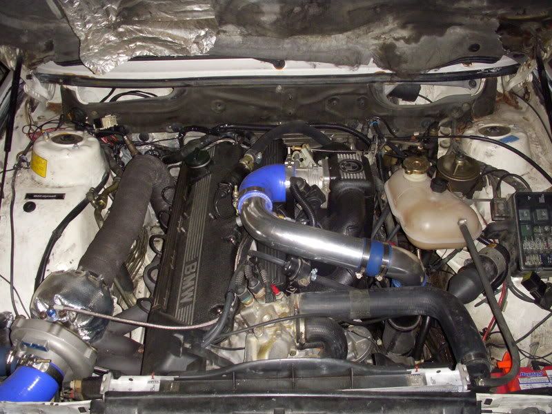
Updated engine bay pics from this evening. Still need to do a bit of cleaning though and add the rest of my thermal wrap on the wiring harness now that all of the MS stuff is working.
The car is running and driving however, my cheapo laptop died so I haven't been able to drive the car since last week. Fortunately today I was able to borrow a laptop for a while so I should be able to get some more tuning done this weekend. Closed loop idle is nice and I have some of the low kPa/low rpm map sorted out. Megalogviewer is awesome!
Gauge pod install. I think I am going to swap out the water temp for oil pressure, I just had the temp gauge when my stock gauge stopped working but its all good now. For now though it will work.

Updated engine bay pics from this evening. Still need to do a bit of cleaning though and add the rest of my thermal wrap on the wiring harness now that all of the MS stuff is working.

The car is running and driving however, my cheapo laptop died so I haven't been able to drive the car since last week. Fortunately today I was able to borrow a laptop for a while so I should be able to get some more tuning done this weekend. Closed loop idle is nice and I have some of the low kPa/low rpm map sorted out. Megalogviewer is awesome!
-
babisbabou
- Posts: 365
- Joined: Jul 15, 2006 6:43 AM
- Location: Greece.athens
-
babisbabou
- Posts: 365
- Joined: Jul 15, 2006 6:43 AM
- Location: Greece.athens
I drilled and tapped the oil filter housing as outlined in Shawn D.'ssender install page. I just used a 1/8 npt to -4 AN adapter and ordered a set of oil inlet and outlet flanges for the turbo. It made for a clean and simple install. I think the only pic I have is the one I posted above in this thread. The turbo drain on the other hand is a little more elaborate.
-
babisbabou
- Posts: 365
- Joined: Jul 15, 2006 6:43 AM
- Location: Greece.athens
Thank you very match m8 for the guide i appreciate itBig Bronze Rim wrote:I drilled and tapped the oil filter housing as outlined in Shawn D.'ssender install page. I just used a 1/8 npt to -4 AN adapter and ordered a set of oil inlet and outlet flanges for the turbo. It made for a clean and simple install. I think the only pic I have is the one I posted above in this thread. The turbo drain on the other hand is a little more elaborate.
Thanks, it turned out pretty well.turbodan wrote:Well done. The plumbing looks quite clean.
A little update - after acquiring another laptop for tuning I have been plagued with a major misfire issue that basically makes the car undriveable. As of tonight I figured out what the problem was. For anyone who cares or for future reference for those building their own MS2/extra setup.
The problem -
I have been getting severe ignition breakup and replaced my coil. Well, it seems as though that was not the issue. I am beginning to think it is something internal to MS itself. I am running a 330ohm pull up resistor on the ignition driver, dwell is set at 2.1 sec.The car starts and idles great but if revved up to any rpm and allowed to sit there it begins to break up and misfires terribly, even revving the engine with no load. While this is occuring the VB921 is getting extremely hot (~130F). If allowed to return to idle and cool off, it will idle fine but any constant rpm or significant load and it repeats the misfire all over. I am not sure if it is a hardware problem on the board(incorrect pull up ckt, bad vb921, etc), or something else. I should also note that my tach, driven off JS11 has gotten very jumpy also.
Also, can a vb921 be dying, but still run the car at idle?
The solution -
I think have solved my problem and I do feel like somewhat of a doofus. I wired my ignition driver as per the MS2 manual here in the internal board wiring section, only I used a 330ohm resistor. However, I seemed to have missed one seemingly critical piece of information - D14 needs to be set as spark output A in Megatune if using this ignition configuration. I had mine set to js10 and removed its jumper and once switched to D14 all of my issues have seemingly gone away. Also, the vb921 stays cool to the touch during operation with no ignition breakup at all. I haven't driven the car around other than in and out of the garage, but I could not reproduce the symptoms that I have been having just free revving in the driveway. I really do hope this is the end of one problem so I can get on with the whole process of actually tuning the car!
-
M. Holtmeier
- Posts: 3025
- Joined: Mar 11, 2007 3:06 AM
- Location: Dallas, Texas
Glad to hear you got it!
I had a feeling it was a software setting that only you could catch from your hardware configuration. I accidentally hit the close button on a rev limit screen instead of "x"-ing out and it defaulted to -10 degrees timing above 100 rpm. Took me half an hour to figure out why car wouldn't start.
Looking forward to seeing maybe a dyno sheet or video of it in action!
Man, it usually is the simple little things that make you chase your tail. However, I will say that through diagnosing these problems I have become very familiar with the internal workings of MS and am better for it. I am looking forward to actualyl starting the tuning process and getting the car on my friends Dyno Dynamics dyno and do some steady state tuning once I have decent, safe base tune. Should be fun!grsmonkey wrote:Glad to hear you got it!
I had a feeling it was a software setting that only you could catch from your hardware configuration. I accidentally hit the close button on a rev limit screen instead of "x"-ing out and it defaulted to -10 degrees timing above 100 rpm. Took me half an hour to figure out why car wouldn't start.
Looking forward to seeing maybe a dyno sheet or video of it in action!


