Noob M30B35 Build

E28 technical advice asked and given! Troubleshooting, modifications and more.
Post Reply
tn535i
Posts: 5590
Joined: Jul 14, 2006 1:30 PM
Location: Middle Tennessee

Post by tn535i »

I ignore people who ask for attention ;)

You are doing great work, sorry I missed some of the ? and answer sessions.

Sorry to say this now but I thought most would say to do the oil pan AFTER the timing covers. You might have a time getting the lower in correctly now. I also think most use a little sealant in the corners of those.where the head and cover gaskets meet.
davintosh
Posts: 13948
Joined: Jan 28, 2009 1:05 AM
Location: Sioux Falls, SD
Contact:

Post by davintosh »

cek wrote:Like most questions I ask in this thread, I figure I'm not going to get any answers. Sometimes I wonder if people are actually reading this. Or maybe no one likes me.
I've been subscribed for a long time and read every update (or at least ogle the pictures.) The whole thread has been incredibly instructive. I don't answer the questions simply because I don't have good answers for you.

Keep up the good work, Charlie. :up:
Mike W.
Posts: 27200
Joined: Feb 12, 2006 12:00 PM
Location: California Whine Country

Post by Mike W. »

Coldswede wrote:I think "That" might be the reason you install the seals a slightly different depth. The seal actually wears a low spot in the journal and can cause a leak.
That's my take on it. But if there is minimal wear it shouldn't be a problem regardless. As far as keeping up on your thread, I try, but sometimes I miss stuff. :laugh: OK, some might say I miss a lot of stuff, but lets not go there...
Das_Prachtstrasse
Posts: 5616
Joined: Sep 10, 2006 7:06 AM
Location: Melbourne, Doooown Under

Post by Das_Prachtstrasse »

All that work and you didn't repaint the throttle body? :nuts:
ldsbeaker
Posts: 6131
Joined: Mar 25, 2007 10:14 PM
Location: Slicktop City, AZ
Contact:

Post by ldsbeaker »

cek wrote:I know this is a TOTAL noob question, but I just want to be damn sure.

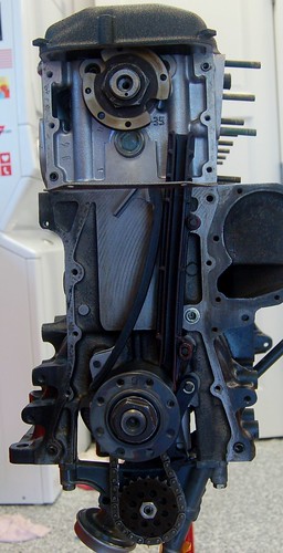
The crank is at TDC when the dowel is at the top?

The camshaft is at TDC when the dowel is at 7pm?

Image
Did you get the answer? SOMEONE will back me up here, or perhaps you got the answer... Remember that the engine is installed at an angle, so 6 o clock (example) on the pictured stand (straight up and down) will be different than 6 o clock in the bay. Your reference should be the INSTALLED 6 o'clock (example).

There was a guy that munched 3 or 4 heads before he realized that was the issue.
tig
Posts: 9285
Joined: Mar 18, 2013 6:25 PM
Location: Durango
Contact:

Post by tig »

ldsbeaker wrote:
cek wrote:I know this is a TOTAL noob question, but I just want to be damn sure.

The crank is at TDC when the dowel is at the top?

The camshaft is at TDC when the dowel is at 7pm?

Image
Did you get the answer? SOMEONE will back me up here, or perhaps you got the answer... Remember that the engine is installed at an angle, so 6 o clock (example) on the pictured stand (straight up and down) will be different than 6 o clock in the bay. Your reference should be the INSTALLED 6 o'clock (example).

There was a guy that munched 3 or 4 heads before he realized that was the issue.
I would appreciate a definitive answer. I've looked at Bentley's 6 ways to Sunday and have searched the forums and have not found anything that makes it super clear. Based on what I've read I think I have it correct in the picture above.
Mike W.
Posts: 27200
Joined: Feb 12, 2006 12:00 PM
Location: California Whine Country

Post by Mike W. »

I always put the harmonic balancer on to see. It's got a line in it that should point straight up in the center to a corresponding mark in the casting of the lower timing cover. It's like you're doing things out of sequence.
tig
Posts: 9285
Joined: Mar 18, 2013 6:25 PM
Location: Durango
Contact:

Post by tig »

Mike W. wrote:I always put the harmonic balancer on to see. It's got a line in it that should point straight up in the center to a corresponding mark in the casting of the lower timing cover. It's like you're doing things out of sequence.
I'm asking about the camshaft, not the crank.
slammin_e28
Posts: 6135
Joined: Aug 05, 2007 4:57 PM
Location: 24477

Post by slammin_e28 »

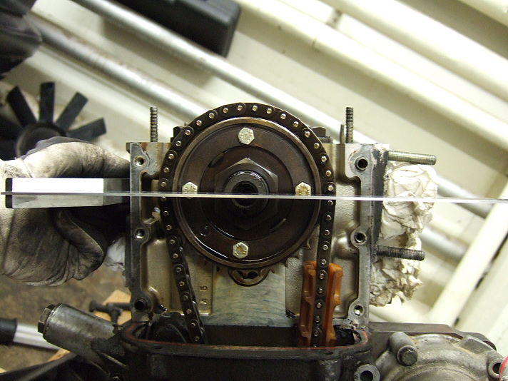
I did mine like this. Of course I turned it over by hand many many times to be sure.

Image

http://www.exx.se/techinfo/timing/
tig
Posts: 9285
Joined: Mar 18, 2013 6:25 PM
Location: Durango
Contact:

Post by tig »

Got all my gaskets this week. Thanks Blunt & Strictly BMW.

Based on y'alls input I pulled the oil pan and did the lower covers first. I also used Permatex.

Image

Image

Image

Once the permatex is dry I'll clean the excess off.
Speedster990
Posts: 69
Joined: Jul 07, 2013 9:06 PM
Location: Provo, UT

Post by Speedster990 »

I have read every post on this thread. Keep up the excellent work!
LarryM
Posts: 1244
Joined: Feb 01, 2008 11:40 AM
Location: SoCal

Post by LarryM »

I too have been reading your thread with great interest.

I think the reason you don't get many replies to your questions is because you're treading in territory where very few of us have ventured: actually doing a complete rebuild on a BMW engine. I've done complete rebuilds (w/ extensive mods) to engines in the past but never on a BMW, so the most I could offer is educated guesses; however I don't think that's what you want or need. I hope that others who have BTDT (with ego in check) will step up when you need them.

I'm looking forward to hearing this beast fire up and seeing some dyno numbers. Good luck!
vinceg101
Posts: 4886
Joined: Jun 20, 2007 2:40 AM
Location: Los Angeles, CA

Post by vinceg101 »

davintosh wrote:
cek wrote:Like most questions I ask in this thread, I figure I'm not going to get any answers. Sometimes I wonder if people are actually reading this. Or maybe no one likes me.
I've been subscribed for a long time and read every update (or at least ogle the pictures.) The whole thread has been incredibly instructive. I don't answer the questions simply because I don't have good answers for you.

Keep up the good work, Charlie. :up:
x2
I plan on venturing into pulling the engine, but mostly for cosmetic reasons and a chance to address some of the other systems. I don't know if I'm brave enough to venture down your path; but I'm happy to live vicariously through this thread.
tig
Posts: 9285
Joined: Mar 18, 2013 6:25 PM
Location: Durango
Contact:

Post by tig »

Thanks for the support folks. I hope this thread will help others. I've learned (and spent...holy cow) so much. I was thinking of going through it and editing posts where I had questions and inserting what I've learned. Or maybe just create a singular FAQ post for the FAQ thread.

You know, barring any more missing parts i might actually get it all together today! CJ is with mom visiting Cal Poly so he won't be able to help but it means i can work uninterrupted.

Kinda freaks me out that its almost done. I have to get my head around the fact i need to pull the engine from vlad...
tig
Posts: 9285
Joined: Mar 18, 2013 6:25 PM
Location: Durango
Contact:

Post by tig »

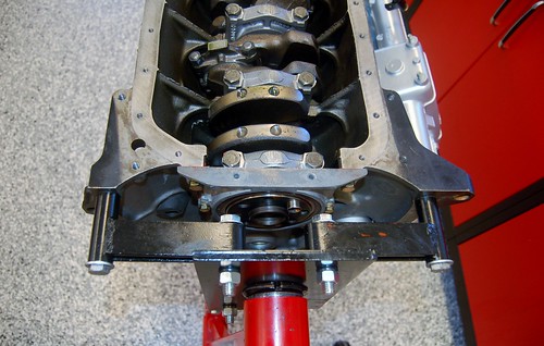
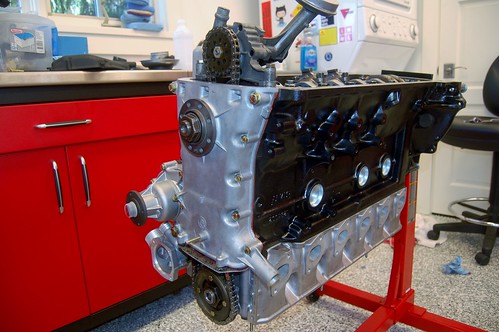
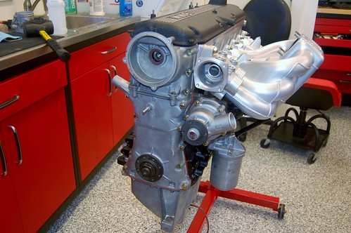
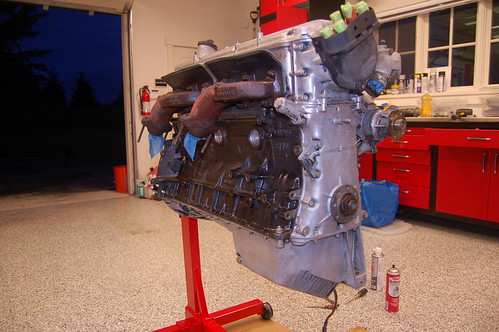
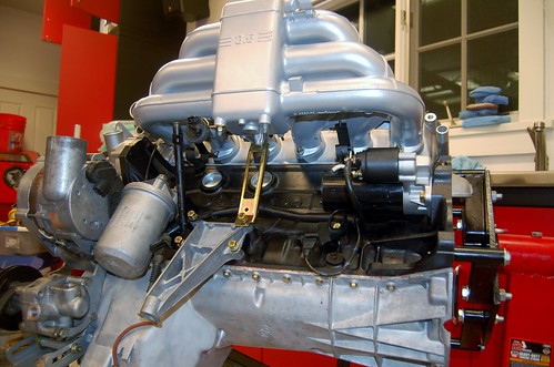
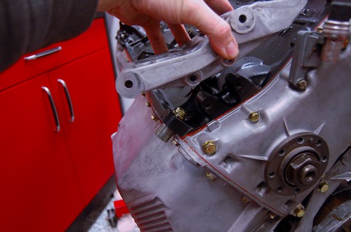
I mounted the intake manifold for good and then decided to get everything on the left side of the engine in place. Along the way I've discovered a few things now have a conundrum.... read on to see.

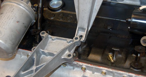
First, the E28/M30B34 left motor mount/support bracket and the bracket that supports the M30B35 intake manifold do not play together. Here's how the B35 block/E32 setup appears:
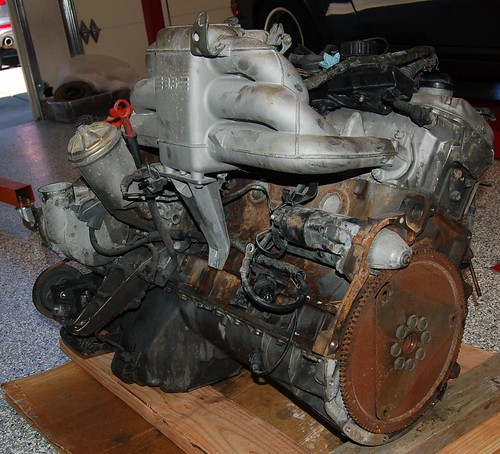
Image

Here's what we have to work with. M30B34 block, M30B35 intake manifold, M30B34/E28 motor mount.
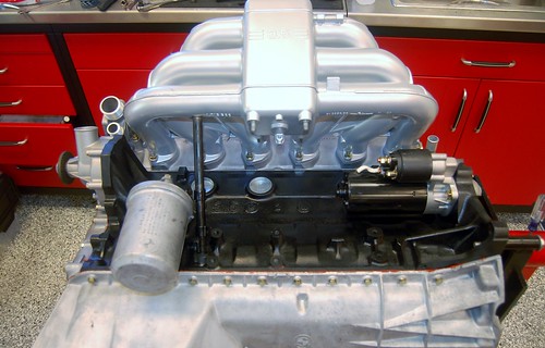
Image

Image

The M30B34 intake manifold is supported by a different sort of bracket; here's a peek inside Vlad:
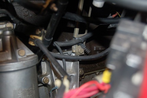
Image

Turns out I had the donor B34 bracket plated, so we're all good there: Just not use the B35 bracket. I'll pull those studs in the B35 manifold since they will just be in the way.

Next, I wasn't sure where to mount the bracket for the oil level sender plug. On the B34 the plug is a little round 2 pin job. On the B35 it's a 3 pin snap in plug. As I poked around I realized I better get the wiring harness on there to see how the wires went. I got the harness out and test fitted it (along with one injector and the fuel rail). Kinda suprised to learn that the late model M30B35 harness is attached to the injectors directly with no other apparent nuts/bolts! Is that right?

At first, I thought the 3 prong female socket on the main harness went to the oil level sensor.
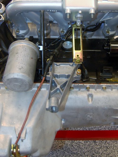
Image

It doesn't. I forgot about the separate wiring harness piece that goes under the intake manifold. On M30B34s this is just a loose collection of wires, but on the B35 they are protected by a pretty hefty steel tube.
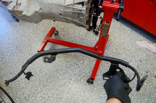
Image

Which leads to the conundrum...

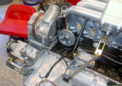
Here's what it all looks like test fitted:
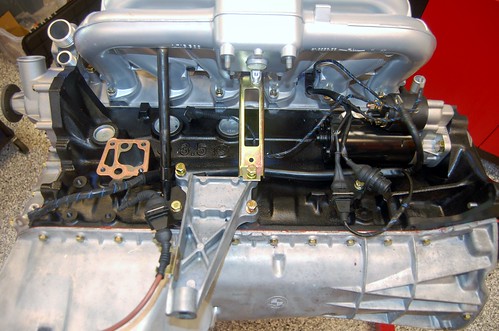
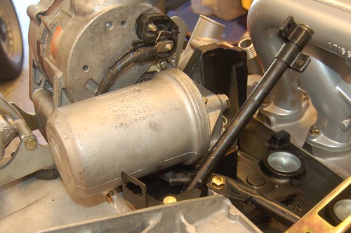
Image

Note I had to remove the oil filter housing.

It turns out that this B35 wire-harness tube interferes with the B34 oil filter housing. They simply cannot be used together as-is.

Here's the B34 housing set in place. Note that it's not bolted in, because it can't be: the steel tube is blocking it.

I have two choices:

1) Bend the steel tube so it fits behind the housing.
2) Go back and re-visit using the B35 oil filter housing.

The reason I went with the B34 housing was it fits the M30B34 block and the B35 housing ALMOST fits the B34 block (and B34 gasket).
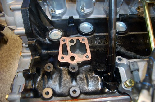
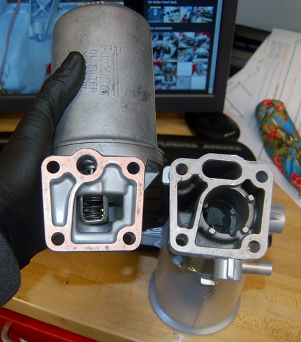
Image

Image

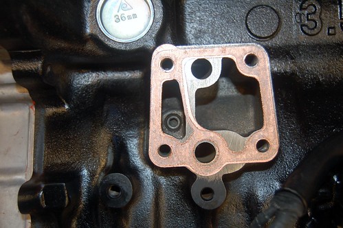
Here's what the B35 block looks like:
Image

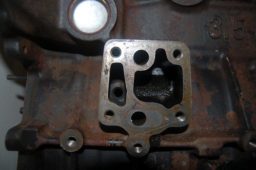
And the B34:

Image

Note the B34 has a hex screw filling the hole in the left passage. But I checked the B35 housing and there is no function on it where oil moves through there.

(RealOEM shows the screw in B34 drawings, but does not show it in B35 drawings. What's it for?)

My intuition tells me the following: I can use permatex to ensure that the larger hole in the B35 housing is sealed up correctly where the gasket is missing material. Or I could order the B35 specific gasket.

Buy my intuition is not really backed by enough experience or knowledge so I'm pausing and asking YOU.

Should I go the quick & dirty route and just bend the pipe or should I use the neato B35 filter housing by just making sure it seals up correctly?
elcrazon
Posts: 120
Joined: Feb 12, 2006 12:00 PM
Location: San Diego, CA

Post by elcrazon »

When I was installing b35 harness fixings on my b34 I came across this thread: http://www.mye28.com/viewtopic.php?t=57158 which was enough to deter me from trying to use the b35 filter housing on the b34 block. Though, I too have an e24 so I have the ABS pump in the way as well.

So, I went with the b34 housing and lopped about 1-1.5" off the end of the metal tube. I also took a chunk out of the engine mount to attach the b35 support as I didn't trust the b34 support to counteract the b35 intake acting as a lever without the top supports that the b34 intake has. I can probably snap a crappy cell phone picture of those things if you want, but I didn't get any shots while I was doing it.
tig
Posts: 9285
Joined: Mar 18, 2013 6:25 PM
Location: Durango
Contact:

Post by tig »

elcrazon wrote: I can probably snap a crappy cell phone picture of those things if you want, but I didn't get any shots while I was doing it.
That would be super awesome. I'm particularly interested in how you modified the engine mount bracket.

I hadn't considered that the B35 doesn't have the upper arms supporting the intake manifold...
elcrazon
Posts: 120
Joined: Feb 12, 2006 12:00 PM
Location: San Diego, CA

Post by elcrazon »

Here's the alternator to starter tube. Looks like I cut it up to the mounting bracket.
Image

Here's the engine mount/intake brace interface. I cut the back of the mount boss flush to the back of the mount and then trimmed off the bracing on the left side of the brace mounting point. There was enough material left that it felt pretty sturdy on the stand and certainly more sturdy than the b34 brace.
Image
tig
Posts: 9285
Joined: Mar 18, 2013 6:25 PM
Location: Durango
Contact:

Post by tig »

Super helpful. Thanks!

Not sure what I'm going to do about the intake mount. Not a huge fan of hacking away at the engine mount, but I do see that what you did probably didn't compromise it at all.

In other news, I decided that instead of bolting things on and potentially cutting/changing things, I needed to pretty much test fit EVERYTHING.

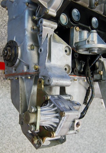
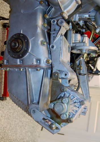
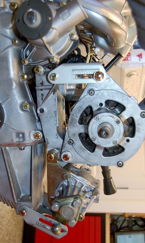
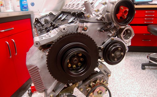
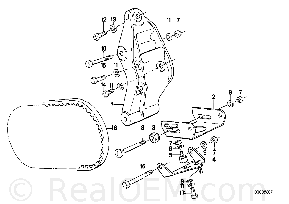
Here's the B35 alternator mount. Note that with a B35 oil pan the PS pump is mounted directly to the pan vs. to the longer B34 alternator/PS pump bracket. I knew this was the case, but hadn't really internalized it until now.

Image

Note that I haven't cleaned up any of these parts yet, and I have new adjustable brackets and gear nuts for both.

ImageDSC_0487

The alternator. I am so tempted to take it apart and paint/powder coat the case...

Image

From the back side

Image
tig
Posts: 9285
Joined: Mar 18, 2013 6:25 PM
Location: Durango
Contact:

Post by tig »

Instead of cutting the pipe, I decided to bend it. I horked it a little in doing so, so I'm going to repaint it so it won't rust, but it all fits fine now.

Image

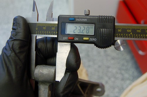
Instead of cutting up the motor mount and intake bracket as @elcrazon did, I think I'm going to fabricate my own bracket. For an E34 the B35 intake bracket mounted flush with the block. For the E28 application we have to make a bracket that is slightly shorter. 23mm shorter:

Image

Getting the geometry of the bracket won't be hard using the original as a template. I figure it could be bent out of a piece of 1/8" steel cut in a triangle shape.
tig
Posts: 9285
Joined: Mar 18, 2013 6:25 PM
Location: Durango
Contact:

Post by tig »

Alternator...

The pulley that was on the donor alternator (140A from an E32) was pretty pitted with rust. Way back when I was disassembling things and I had the alternator tested I decided to buy a new pulley.

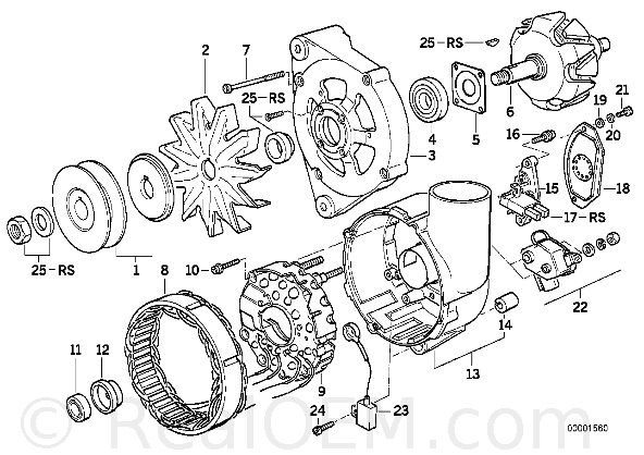
RealOEM diagram:

Image

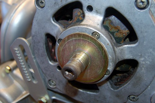
Along the way I also lost the woodruff key (# 25-RS near the top right). As you can see the shaft has a place for it. I remember it falling off when I pulled the pulley and not being able to find it (lesson: do not do paint chips in your garage's epoxy floor...impossible to find small parts).

Image

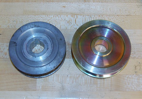
Today I noticed the new pulley does not have a spot for the woodruff key!

Image

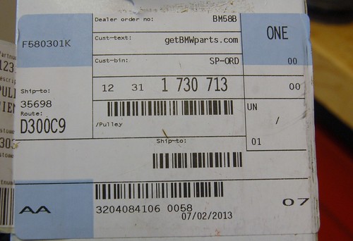
How in the world am I supposed to get the shaft nut tight enough to guarantee the pulley doesn't spin on it!?!? Did I get the wrong pulley? The box it came in shows the correct part # (12311730713).
Image

Test fit just to show shine.
Image
vinceg101
Posts: 4886
Joined: Jun 20, 2007 2:40 AM
Location: Los Angeles, CA

Post by vinceg101 »

cek wrote:The alternator. I am so tempted to take it apart and paint/powder coat the case...
I would provided you can get the case screws out. I tried this with an M5 alt and couldn't un-freeze 2 of the case screws. Gave up and got another one.

I would do it simply because, after all this work, when you look at it later you will curse yourself for not doing it when you had it all apart.
tig
Posts: 9285
Joined: Mar 18, 2013 6:25 PM
Location: Durango
Contact:

Post by tig »

Air Conditioning compressor.

The M30B35 FAQ says:
You can use your m30b34 power steering pump (part number 32411133969), 90A alternator (part number 12311466087), and AC compressor if you use the m30b34 mounting brackets (part number 12311708343 and 64521284953), adjusters, crankshaft pulley (part number 11211258274), and power steering belt (part number ), alternator belt (part number 11221706788), and AC belt (part number 64521711056). 

You can use the m30b35 power steering pump (part number 32411141058), 140A alternator (part number 12311735706), AC compressor, mounting brackets (part number 12311707194 and 64521284953), adjusters, crankshaft pulley (part number 11231716270), and power steering belt (part number 11231709636), alternator belt (part number 11231706668), AC belt (part number 64521722371) from the m30b35, but you will have to do something to the lines for the AC, everything else will work and bolt up however.
I have decided I'm using the AC compressor that's in Vlad instead of the one that came with the B35 donor motor. First, I know the one in Vlad is good. I have no idea of the condition of the donor, but it looks tired. Second, the B35 unit's hose outlets are not the same as the B34 unit; if I used the B35 unit I'd have to modify the AC lines. 3rd, I think I can pull the motor and put the new one in without disconnecting the AC lines at all, ensuring I don't have to recharge the system.

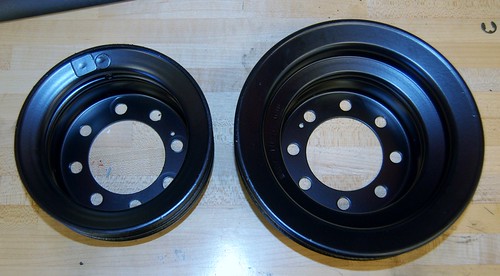
This means I need to use the B34 crankshaft (PS/AC) pully, which is part #11211258274 and is the smaller of the two below. I guess the B35 AC compressor spins faster than the B34 compressor.

Image
tig
Posts: 9285
Joined: Mar 18, 2013 6:25 PM
Location: Durango
Contact:

Post by tig »

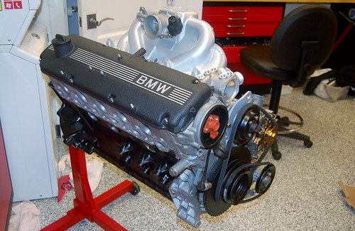
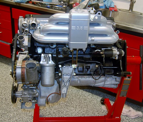
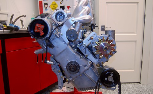
I do believe we are approaching the finish line.

Image

Image

Image

I am sure the next time I do this it will take a fraction of the time. I lost count of the number of times I had to remove the harmonic balancer because I realized there was one more part I had missed putting on.

For example this "Grub screw", #5 in this AC diagram:

Image

I only realized this because I was re-reviewing photos of when we tore down the engine and noticed it on the block:

Image

Here it is installed (after removing the balancer and AC compressor mount).

Image

Image

Note new hose hangers
Image

Way back in this thread I asked about the correct order for assembly. I didn't get any good answers so I just decided it really didn't matter and dug in.

That was a mistake. Not a huge one, but just made it all take longer due to re-work. Here's an order that would make more sense:
  1. Oil pump and chain.
  2. Lower timing chain sprocket, guides, and timing chain.
  3. Lower timing chain cover. Don't forget to install the brackets for the timing sensor and shackle.
  4. Grub screw, AC compressor mount, PS/Alternator mount
  5. Rear main seal.
  6. Oil pan
  7. Install harmonic balancer temporarily so you can see crank TDC. NOTE: in my pic above I am NOT at TDC. The crank dowel pointing up DOES NOT indicate TDC.
  8. Set head to camshaft TDC before installing. TDC means the small dowel pin on camshaft is down and the two face bolts are aligned vertically.
  9. Head.
  10. Upper timing chain cover
  11. The rest is straight forward
tig
Posts: 9285
Joined: Mar 18, 2013 6:25 PM
Location: Durango
Contact:

Post by tig »

I reviewed this thread an found all the questions I asked that were subsequently answered. I've put them all in the M30B35 FAQ here:

http://www.mye28.com/viewtopic.php?p=1246688#1246688
VW+bimmer=bliss
Posts: 850
Joined: Nov 25, 2007 10:18 PM
Location: Racine, Wisconsin

Post by VW+bimmer=bliss »

Just a thought, you might want to do the dual chamber spray bar modification for the rockers. It involves pinching the middle of it and making two smaller chambers instead of one larger one. My rockers are nice and quiet.

http://www.e9coupe.com/tech/spray_bar_fix/70590.html

Oh, and nice work with that engine!
tig
Posts: 9285
Joined: Mar 18, 2013 6:25 PM
Location: Durango
Contact:

Post by tig »

VW+bimmer=bliss wrote:Just a thought, you might want to do the dual chamber spray bar modification for the rockers. It involves pinching the middle of it and making two smaller chambers instead of one larger one. My rockers are nice and quiet.

http://www.e9coupe.com/tech/spray_bar_fix/70590.html

Oh, and nice work with that engine!
Yea, I've contemplated this. I'm not convinced. It SEEMS logical that it should work, and there's lots of people who claim their engine has not blown up as a result, but there's also those BMW engineers who are/were pretty damn smart.
slammin_e28
Posts: 6135
Joined: Aug 05, 2007 4:57 PM
Location: 24477

Post by slammin_e28 »

cek wrote:
Yea, I've contemplated this. I'm not convinced. It SEEMS logical that it should work, and there's lots of people who claim their engine has not blown up as a result, but there's also those BMW engineers who are/were pretty damn smart.
Those same guys made the M20. :brick:
tig
Posts: 9285
Joined: Mar 18, 2013 6:25 PM
Location: Durango
Contact:

Post by tig »

Assuming I can find time with my son this coming weekend we will be dropping the M30B34 out of Vlad.

I spent some time under the car on the lift this weekend double checking my initial plan, which is to drop the engine from underneath (or, more accurately raising the car from the engine).

Here's the current plan. Would love feedback and pointers to things I've missed. Explicit questions I have are in bold.

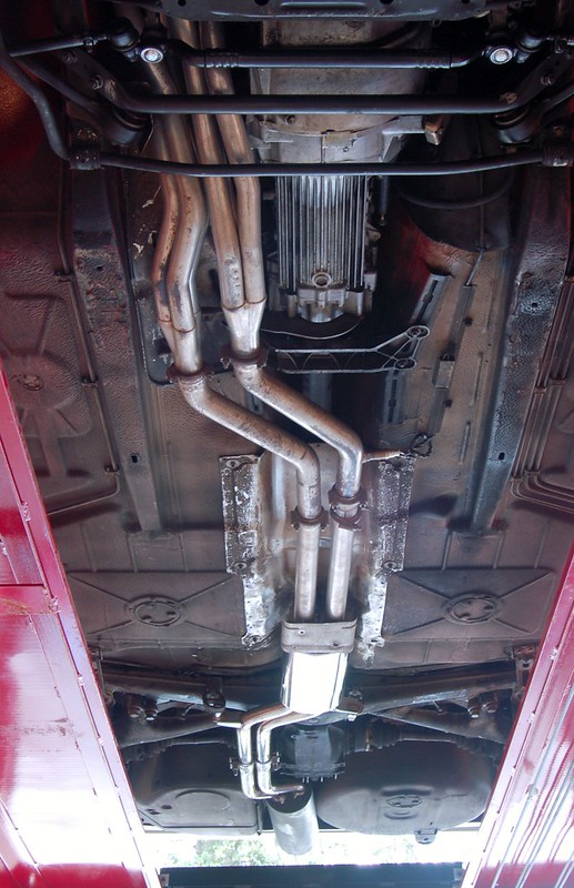
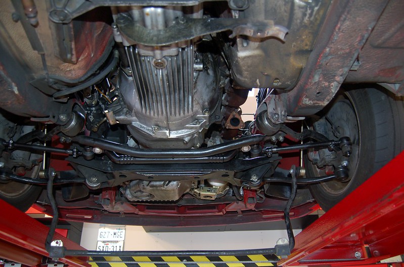
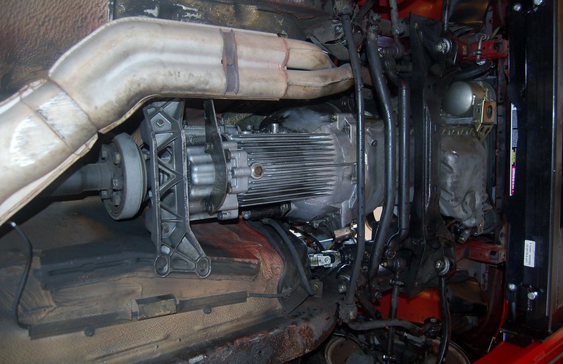
Some under car pics for reference:

Image

Image

Image
  1. Drive car so that it's almost out of gas (getting close) so the amount that has to be drained from the tank is minimal. I'm cleaning the tank and replacing the in-tank pump.
  2. Put car on lift, being careful to center it. There's plenty of room for the widest component (the subframe) but having it perfectly centered will ensure things go smoothly.
  3. Drain coolant.
  4. Remove radiator and fan.
  5. Disconnect cooling system hoses from heater control valve, etc...
  6. Unplug harness from ECU, ground wires, and other connections to free the engine.
  7. Before raising car, remove shift knob, boot, and surround. Do I need to unbolt anything from "above" prior to transmission coming out?
  8. Remove exhaust from headers rearward.
  9. Remove heat shield, which is in pretty sad shape.
  10. Remove drive shaft (I'm replacing it).
  11. Question: Should I bother draining the engine oil? If it sat for, say 3 years, wouldn't it be better to have oil in it than not? This engine probably deserves a re-seal before it goes in another car, but doesn't NEED it.
  12. Remove AC compressor from engine but leave it connected. Tie it out of the way with zip ties or something.
  13. Remove sway bar
  14. Remove sub-frame brace (Which RealOEM helpfully calls the "Rod")
  15. Remove tie-rod center, moving tie-rod ends out of the way.
  16. Remove front wishbone end from subframe, fold out of the way.
  17. Somehow disconnect power steering box from subframe (or steering column shaft from steering box). What's the right thing to do here?
  18. Using bridge jack on framerails BEHIND the back of the transmission, lift front of car enough to remove front wheels. This will also cause the engine/tranny to be tilted towards the back a bit.
  19. I have two large (3000lbs?) jackstands and 4 smallish (1500lbs?) jackstands.
  20. The two large stands will support the subframe, placed just inside of where the front wishbone arms connect.
  21. Three of the smaller stands will support the transmission. One on front of tranny where the fins end (with a block of wood for protection) and two on each end of the transmission support bracket. Nice stable triangle.
  22. Lower lift so jackstands under subframe are stressed, actually bearing (just barely) the weight of the front of the car. Jackstands for transmission can be adjusted to fit now.
  23. Crawl under (clearance will actually be pretty good given how tall my large jack-stands can go) and unbolt transmission support. Tranny/engine should now pivot on motor mounts and tranny should rest on small jack stands.
  24. Unbolt the subframe from the frame.
  25. Raise lift. Engine & transmission cradled by subframe on the jack stands, should stay put.
  26. Using combination of hoist & stands disconnect the transmission and the subframe from the engine. Store engine somewhere.
Last edited by tig on Apr 22, 2014 2:25 AM, edited 1 time in total.
tig
Posts: 9285
Joined: Mar 18, 2013 6:25 PM
Location: Durango
Contact:

Post by tig »

slammin_e28 wrote:
cek wrote:
Yea, I've contemplated this. I'm not convinced. It SEEMS logical that it should work, and there's lots of people who claim their engine has not blown up as a result, but there's also those BMW engineers who are/were pretty damn smart.
Those same guys made the M20. :brick:
I don't get your point. If the M20 has a bifurcated oil spray bar, then they had a reason for doing it int he M20. But not in the M30. They were basically the same guys. This means they explicitly decided NOT to bifurcate it.
elcrazon
Posts: 120
Joined: Feb 12, 2006 12:00 PM
Location: San Diego, CA

Post by elcrazon »

cek wrote: Somehow disconnect power steering box from subframe (or steering column shaft from steering box). What's the right thing to do here?
I'd just unbolt the universal joint from the steering box input. Not sure how you'd easily support the steering box if you removed it from the subframe.
tig
Posts: 9285
Joined: Mar 18, 2013 6:25 PM
Location: Durango
Contact:

Post by tig »

elcrazon wrote:
cek wrote: Somehow disconnect power steering box from subframe (or steering column shaft from steering box). What's the right thing to do here?
I'd just unbolt the universal joint from the steering box input. Not sure how you'd easily support the steering box if you removed it from the subframe.
Perfect. Thanks!
slimdevil27
Posts: 935
Joined: Nov 12, 2011 6:21 PM
Location: WA

Post by slimdevil27 »

I spent some time under the car on the lift this weekend double checking my initial plan, which is to drop the engine from underneath (or, more accurately raising the car from the engine).
ABSOLUTELY NOT.

You have a drive on lift. Not a frame lift. Once you start unbolting the upper and lower control arms there is nothing to keep the wheels straight except the upper strut bushing. You remove those control arms with weight on the wheels and they will roll forward and buckle. Or worse roll and shift to the side and dump your car on the floor. What you are thinking will only work on a two post lift, that would be supporting the body allowing you to take the wheels off and drop the struts with the spindles and control arms still bolted in, removing only the calipers.

Pull the engine out the top.
tig
Posts: 9285
Joined: Mar 18, 2013 6:25 PM
Location: Durango
Contact:

Post by tig »

slimdevil27 wrote:
I spent some time under the car on the lift this weekend double checking my initial plan, which is to drop the engine from underneath (or, more accurately raising the car from the engine).
ABSOLUTELY NOT.

You have a drive on lift. Not a frame lift. Once you start unbolting the upper and lower control arms there is nothing to keep the wheels straight except the upper strut bushing. You remove those control arms with weight on the wheels and they will roll forward and buckle. Or worse roll and shift to the side and dump your car on the floor. What you are thinking will only work on a two post lift, that would be supporting the body allowing you to take the wheels off and drop the struts with the spindles and control arms still bolted in, removing only the calipers.

Pull the engine out the top.
Appreciate you taking the time and providing input. However you've missed an important point, probably exacerbated by me goofing in my ordering above. I said:
  1. Remove sway bar
  2. Remove sub-frame brace (Which RealOEM helpfully calls the "Rod")
  3. Remove tie-rod center, moving tie-rod ends out of the way.
  4. Remove front wishbone end from subframe, fold out of the way.
  5. Somehow disconnect power steering box from subframe (or steering column shaft from steering box). What's the right thing to do here?
  6. Using bridge jack on framerails BEHIND the back of the transmission, lift front of car enough to remove front wheels. This will also cause the engine/tranny to be tilted towards the back a bit.
I meant:
  1. Using bridge jack on framerails BEHIND the back of the transmission, lift front of car enough to remove front wheels. This will also cause the engine/tranny to be tilted towards the back a bit.
  2. Remove sway bar
  3. Remove sub-frame brace (Which RealOEM helpfully calls the "Rod")
  4. Remove tie-rod center, moving tie-rod ends out of the way.
  5. Remove front wishbone end from subframe, fold out of the way.
  6. Somehow disconnect power steering box from subframe (or steering column shaft from steering box). What's the right thing to do here?
Yes, I have a 4 post drive on lift. But that lift has a rolling bridge jack that will allow me to support the car from the frame rails. I lift the front end ALL the time using this. E.g. here's a picture of my 528e thusly suspended:

Image

In that pic I have the bridge jack pretty far forward, at the jack points. But there's no reason why I can't have it further back. In fact, if I didn't have the bridge jack, but had a way of lifting the car, I could use jack stands at the lift points, sitting on the ramps. But I don't have to do that because I have the bridge jack.

Better pic of the bridge jack:

Image
wkohler
Posts: 50924
Joined: Oct 05, 2006 11:04 PM
Location: Phönix, Arizona, USA
Contact:

Post by wkohler »

This has disaster written all over it.
tig
Posts: 9285
Joined: Mar 18, 2013 6:25 PM
Location: Durango
Contact:

Post by tig »

wkohler wrote:This has disaster written all over it.
Gee, thanks Chris for providing such deeply insightful and useful commentary.
wkohler
Posts: 50924
Joined: Oct 05, 2006 11:04 PM
Location: Phönix, Arizona, USA
Contact:

Post by wkohler »

I am glad you found it useful. I strive to be helpful whenever and wherever I can. They love me around here. They think I'm a swell guy.
tig
Posts: 9285
Joined: Mar 18, 2013 6:25 PM
Location: Durango
Contact:

Post by tig »

wkohler wrote:I am glad you found it useful. I strive to be helpful whenever and wherever I can. They love me around here. They think I'm a swell guy.
Who, exactly, is "they"?

Also, I'm reminded of a movie quote involving the word "inconceivable", but with "inconceivable" replaced with "love" (oh, I just realized this is probably lost on you since you don't seem to watch TV or movies).
wkohler
Posts: 50924
Joined: Oct 05, 2006 11:04 PM
Location: Phönix, Arizona, USA
Contact:

Post by wkohler »

I've never seen the Princess Bride. I've seen The Breakfast Club though.

It is much easier and safer to pull the motor out the top. You are overthinking it. I bought a two post lift to drop subframes. At this rate, that will never happen.
Last edited by wkohler on Apr 22, 2014 2:38 AM, edited 1 time in total.
slimdevil27
Posts: 935
Joined: Nov 12, 2011 6:21 PM
Location: WA

Post by slimdevil27 »

Any particular reason not to pull it out the top?

Reminds me of this...

After nearly forty years in practice as a gynecologist,
John decided he had enough money to retire and take up
his real love, auto mechanics. He left his practice,
enrolled in auto mechanics school, and studied hard.
The day of the final exam came and John worried if he
would be able to complete the test with the same
proficiency as his younger classmates. Most of the
students completed their exam in two hours. John, on
the other hand, took the entire four hours allotted.
John tossed and turned in bed that night, dreading the
next morning when the exam scores would be returned.

The following day, John was delighted and surprised to
see a score of 150% for his exam.

John spoke to his professor after class. "I never
dreamed I could do this well on the exam. But tell me,
how did I earn a score of 150%?"

The professor replied, "I gave you 50% for perfectly
disassembling the car engine. I awarded another 50% for
perfectly reassembling the engine. I gave you an
additional 50% for having done all of it through the
muffler."
Post Reply