Page 1 of 2
Posted: May 29, 2011 4:19 PM
by abdoosh00
If I was working on it I would do it to work on both on MS and motronic, taking a reading from the wideband is good enough, but wont work on pre-86 cars as they dnt have one.
not sure wut you mean by keep all of the output straight though!
Posted: May 29, 2011 7:15 PM
by hinterländer
abdoosh00 wrote:7-segment is much better and clearer. a 16x2 will be too small to see without getting ur head closer to the cluster, u dnt wanna do that while driving.
I think battery voltage and coolant temp or oil temp are easy to to read directly from sensors. for the AFR you will need to know the "air volume" to resistance relation read from AFM flap, could be done but need sum kind of air measurement tool for correct calibration.
x2 on the 7-segment. I still am trying to see the wisdom in oil temp though. Already have a coolant temp gauge, too. So that still leaves battery voltage, oil pressure, and AFR. My '87 uses Motronic 1.0, so I'm still using a narrow band O2 sensor which isn't as precise as wideband, so I'm still debating the usefulness for a stock DME (perhaps to monitor the condition of O2 sensor?); but people using tuner chips may find it useful. AFAIK, there is NO oil pressure sensor on this motor (M30B34) from the factory?
Posted: May 29, 2011 8:02 PM
by Xenocide
If I was working on it I would do it to work on both on MS and motronic
Well, it'd be great to use it on MS and motronic, but motronic has no serial connection. You could collect data from individual sending units, but you'd have to splice into the factory harness, and in the interest of saving pins on the controller I'd want to use serial to get 80% of the data using only 2 pins. Plus I have been toying with the idea of programming maps over serial (purely a pipe dream now, but certainly possible).
taking a reading from the wideband is good enough, but wont work on pre-86 cars as they dnt have one.
I figure anyone who is interested in realtime AFR has a wideband...
not sure wut you mean by keep all of the output straight though
I meant that without labels it'd be difficult to determine which number is which. You could have LED indicators or something, which would work okay I suppose, but it seems unpolished next to a full display*
*
If it's remotely readable
As soon as I get a working prototype I'd love some ideas to make it more usable by more people, but right now I'm just playing with my own setup. Honestly this thing would be so much damned work for other people to install, it'd probably be more trouble than it's worth for most people, but hey it could be cool right?
EDIT:
AFAIK, there is NO oil pressure sensor on this motor (M30B34) from the factory?
Correct. Oil pressure switches were, but no analog sensors.
EDIT #2: Same goes for the m20
Posted: May 29, 2011 9:07 PM
by abdoosh00
As soon as I get a working prototype I'd love some ideas to make it more usable by more people, but right now I'm just playing with my own setup. Honestly this thing would be so much damned work for other people to install, it'd probably be more trouble than it's worth for most people, but hey it could be cool right?
Cool...definitely.
Trouble...what isnt with a 25 yrs old car

.
If you get smthng workin ill be happy to see. If anythng could be adjusted ill try to help as well. PIC18F you said, using Assembler or C?
Posted: May 29, 2011 9:13 PM
by Xenocide
Been working on it in C (C18 compiler). I've not done much C before, and never worked with PICs so it's been slow going, but it's fun. I had half a mind to just ditch the PIC and use an arduino, but that'd be just way too easy

(and too few I/Os to play with)
Posted: May 29, 2011 9:31 PM
by mooseheadm5
Just skimming since I have lots to catch up on.
No E28 has a wideband O2 sensor. You will need a wideband controller if you want usable AFR. Most wideband controllers can output a narrow band signal for the DME to use.
You need to add an oil pressure sender and an oil temp sender. The oil pressure sender can be had with a low pressure light output. Just as an aside, the pressure sender is pretty darn expensive. That is the one thing that I can't control. I am still working with someone on a driver for the mpg gauge to turn it into a multi function gauge, but it is not an option on an M5 so I am exploring this option as well.
Posted: May 29, 2011 9:54 PM
by abdoosh00
Been working on it in C (C18 compiler). I've not done much C before, and never worked with PICs so it's been slow going, but it's fun. I had half a mind to just ditch the PIC and use an arduino, but that'd be just way too easy LOL (and too few I/Os to play with)
When its this low level and no calculations involved I prefer using assembly, its just very straight to the point, short code and fast. Not saying the C18 is bad or anythng, just depends on the application really, you can do anything using both if you look at it this way. Never worked with arduino really, but heard good things on it.
No E28 has a wideband O2 sensor. You will need a wideband controller if you want usable AFR. Most wideband controllers can output a narrow band signal for the DME to use.
Xenocide is using MS in which I think you will need to convert the NB sensor to a WB, if im not mistaken, but you guys knw better.
Posted: May 29, 2011 10:00 PM
by mooseheadm5
abdoosh00 wrote:
Xenocide is using MS which I think converts the NB sensor to a WB, if im not mistaken, but you guys knw better.
I know. I was addressing the comment you made that said pre-86 cars have NB when in fact all E28s came from the factory with NB. In MS, you can run WB and just tell the program what signal you are inputting. You still need a wideband controller to run the sensor, though. You usually get a spare output from the controller to run a gauge.
Posted: May 29, 2011 11:59 PM
by Xenocide
abdoosh00 wrote:When its this low level and no calculations involved I prefer using assembly, its just very straight to the point, short code and fast. Not saying the C18 is bad or anythng, just depends on the application really, you can do anything using both if you look at it this way. Never worked with arduino really, but heard good things on it.
I'm just getting into this lower level stuff (PICs, PLCs, etc.), I come from a background in Java, C++, PHP, and (when held at gunpoint) VB, so I figured ANSI C would be more friendly and readable. I'll get to the nitty gritty soon

I finally got a chance to sit down and get the LCD to initialize and output properly, it is VERY readable at varying distances and in varying light conditions. I still need to lay hands on an old (first gen) OBC to do the keypad interface and I still haven't touched the serial libraries for the pic18f, but it's a win for me just to get the LCD working.
Posted: Apr 25, 2012 11:33 PM
by cleeves
OK. So this thought is back in my head a year later. I'm confident I can do the digital one where the autotragic lights are.
Buy four of these.
http://www.ebay.com/itm/10Pcs-3-Bit-Dig ... 517wt_1189
Buy this.
http://www.ebay.com/itm/NEW-2-52mm-BLUE ... 285wt_1189
Buy this.
http://www.ebay.com/itm/NEW-Universal-2 ... 378wt_1189
Buy this.
http://www.ebay.com/itm/NEW-2-52mm-BLUE ... 4346wt_956
Buy this.
http://www.ebay.com/itm/NEW-DRAGON-2-52 ... 275wt_1189
Scrap the blue displays, install ribbon cables going from those large meters to the new red displays. Find a remote location for everything except the tiny red displays (only 0.59" tall) and their corresponding ribbon cables.
Make room for (4) red digital displays. Oil press, Oil temp, Voltage, Water temp.
So.... Does anyone have an broken cluster that I can cut up for retrofitting? My car is a DD so I can't have it apart for too long when I plan out how I'm going to cut apart the cluster and fit the wires. The goal is to plan it out first, and install on my car in a weekend. I think I can do it.
If the results are good, I may look into retrofitting more clusters and selling them. Wouldn't be a bad side job in college. If all goes as planned, the person providing me with the scrap cluster will get first dibs on this. I don't know what the demand is but I think it's a great idea or otherwise I wouldn't have suggested it.
Henry
Posted: Apr 26, 2012 12:57 AM
by mooseheadm5
That's easily the most convoluted way to do this. It would be way easier to have Xenocide program an Arduino to process the signals and drive the displays. Probably cheaper, too.
Posted: Apr 26, 2012 1:42 AM
by cleeves
mooseheadm5 wrote:That's easily the most convoluted way to do this. It would be way easier to have Xenocide program an Arduino to process the signals and drive the displays. Probably cheaper, too.
Good idea. Just read the wikipedia article on the Arduino. Damn thing is sweet. I've learned a lot about math in school but I haven't done much implementation yet. Let me see what I can come up with, I can write C++ and Matlab pretty well.
Henry
Posted: Apr 26, 2012 2:04 AM
by S14
Posted: Apr 26, 2012 6:02 PM
by cleeves
Well alright.
So, say at MAX, I have 5 different 4-digit digital displays.
Oil Temp
Oil Press
Water Temp
Volts
Fuel Level
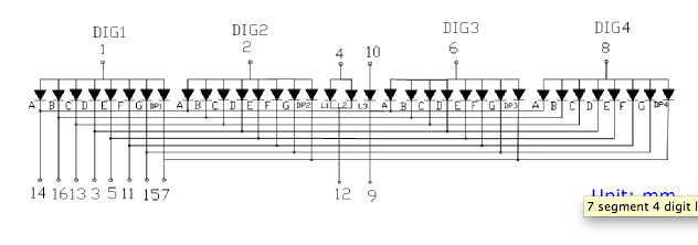
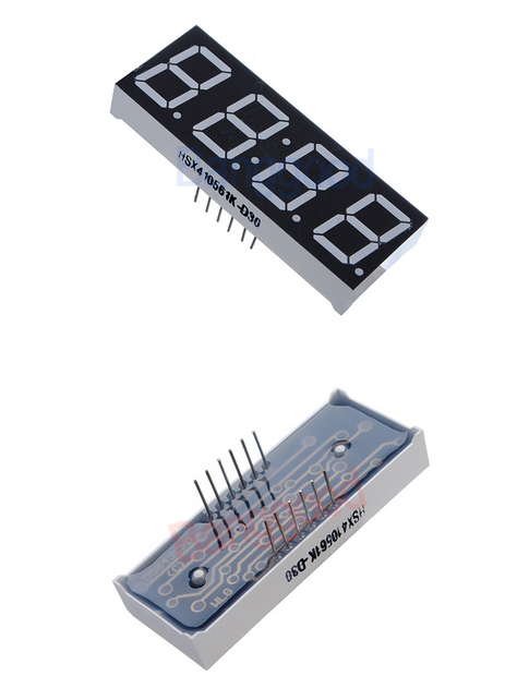
Here is the schematic for a 12 pin 4 digit 7 segment display. Well actually 8 segment because of the decimal. (disregard pins 4, 9, 10 and 12 they are irrelevant)
Here is a picture:
So, if my assumptions are correct, I can connect the 14, 16, 13, 3, 5, 15, 11, 7 pins to the corresponding 14, 16, 13, 3, 5, 15, 11, 7 pins on the other 4 displays.
The 1, 2, 6, 8 pins must each have their own wire running to the Arduino along with each other 1,2,6,8 pin on the other 4 displays.
So basically:
For 1 display I need 12 wires.
For 2 displays I need 16 wires.
For 3 displays I need 20 wires.
For 4 displays I need 24 wires.
For 5 displays I need 28 wires.
The Arduino MEGA 2560 has 14 analog inputs and 56 digital ones. Only $25.
I did some reading on the Arduino, getting the analog inputs to read on the computer is going to be cake. They convert 0 to +5 volt into digital memory of numbers 0-1024. With 0 volts being 0, +2.5 volts being 512, +5 volts being 1024. Simple voltage drop circuit if it's too high or OP amp if it's too low (or the range is crap).
These displays seem a bit more complicated.
Thoughts?
Henry
Posted: Apr 26, 2012 8:45 PM
by Xenocide
BCD encoders, my friend. A regular arduino should be fine using a couple of encoders. Of course with the megas being so cheap with chinese manufacturers and all, it's almost worth it to just keep it on one board.
http://youtu.be/1vhDgymZH8U
I finally got around to recording a simulation of the PIC18F based system I've been designing. It's running a demo right now, just to display the mapping of the different variables. It takes input from 10 bit ADCs, right now I've got all the data stored in 8 bit variables to save space, then mapped to their various ranges for the menu system.
I'll be happy to help if you want to pursue this. I've thought about this sort of system for a LONG time now.
EDIT: What you're talking about is called multiplexing, and it's actually pretty clever, it's a great way to reduce the required IO pins.
Posted: Apr 26, 2012 9:13 PM
by cleeves
Xenocide wrote:BCD encoders, my friend. A regular arduino should be fine using a couple of encoders. Of course with the megas being so cheap with chinese manufacturers and all, it's almost worth it to just keep it on one board.
http://youtu.be/1vhDgymZH8U
I finally got around to recording a simulation of the PIC18F based system I've been designing. It's running a demo right now, just to display the mapping of the different variables. It takes input from 10 bit ADCs, right now I've got all the data stored in 8 bit variables to save space, then mapped to their various ranges for the menu system.
I'll be happy to help if you want to pursue this. I've thought about this sort of system for a LONG time now.
EDIT: What you're talking about is called multiplexing, and it's actually pretty clever, it's a great way to reduce the required IO pins.
Yes I have studied the BCD encoder. Here is why I didn't propose it.
You need one BCD encoding chip for each of the digits of display. 4 digits per display multiplied by 5 displays is 20 chips. And you still have 4 data wires per BCD unit plus a voltage and a ground. So 20 wires plus voltage and ground. And a wire to make em all go on at once or to make em all go out for testing. You still have 24 wires.
With these 12 pins, look at the schematics. Each of the 4 digits in each display is already multiplexed inside the unit. You can't just disconnect pins 14,15,13,3,5,11,15,7 from each individual digit. So you'd have to tear it apart to fit a BCD chip in it. Plus you have BCD chips right there on the display board. It's cramped as hell inside the SI, that's why I think the multiplexing is better even if you have 28 wires and not 24.
Is there something I'm missing here?
Oh and thanks for the help offer, I might take you up on it. Did you use LabVIEW for your simulation?
Another issue with the BCD chip encoding. You can only put numbers on it. With multiplexing you can light whatever the hell LED's you want. Say you want to program it to dance the lights around when you first start up the car just for show, or put a funny message in it. You can do it with multiplexing.
Henry
Posted: Apr 26, 2012 9:30 PM
by Xenocide
High speed BCDs can be multiplexed themselves, but having taken a closer look at the schematic, I get it. That should work great, and I would have to agree that the arduino mega would be a fantastic microcontroller for the application. After much debate about this, I did the typical thing that an engineer does: overcomplicated the shit out of it. I sort of wanted to work with a 16x2 or 20x4 display anyway, and I wanted a lower development cost. This is what got me interested in the PIC18 chips to begin with.
If you just loved the 7 segment displays the arduino mega is definitely a solid option. If it were me I'd even do it quick and dirty program in the arduino IDE rather than mucking around with C programming. FWIW, you could achieve similar results to what I've posted on a 16x2 LCD with the arduino in a few lines of code. There are libraries already written, I believe.
Posted: Apr 26, 2012 9:46 PM
by cleeves
Xenocide wrote:High speed BCDs can be multiplexed themselves, but having taken a closer look at the schematic, I get it. That should work great, and I would have to agree that the arduino mega would be a fantastic microcontroller for the application. After much debate about this, I did the typical thing that an engineer does: overcomplicated the shit out of it. I sort of wanted to work with a 16x2 or 20x4 display anyway, and I wanted a lower development cost. This is what got me interested in the PIC18 chips to begin with.
If you just loved the 7 segment displays the arduino mega is definitely a solid option. If it were me I'd even do it quick and dirty program in the arduino IDE rather than mucking around with C programming. FWIW, you could achieve similar results to what I've posted on a 16x2 LCD with the arduino in a few lines of code. There are libraries already written, I believe.
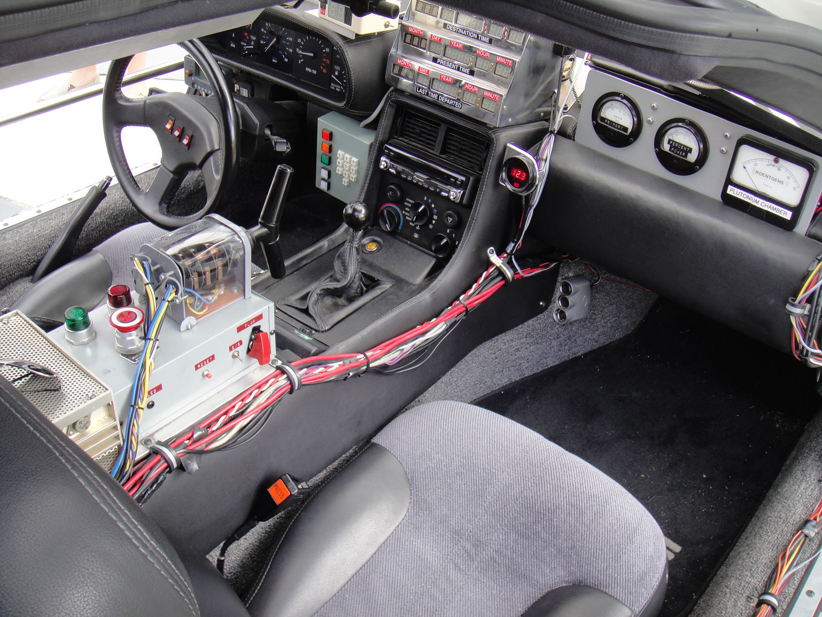
Yeah, I see what you are saying about the 20x4 display. I think the 7 segment ones look way cooler though, especially in an '80s car. After all, they didn't have much of that LCD display or the 20x4/16x2 type stuff back then. Look in the Back to the Future car. All 7 segment displays! (maybe even 16 segment-but none of that crazy 20x4 stuff).
I did the dimensions and if I router out the entire middle rectangle section of the cluster, removing the coolant temp, fuel temp, warning lights, and signals, those 5 displays will fit perfectly. It's easy to read and the digits are red like the cluster lights. Plus I can wire a couple of extra bright LED's in for when the fuel gets too low or the temp gets too high.
I have no idea how to do the IDE programming. I suppose I could try to learn but I already know C++ and if the libraries are there it seems like a decent option.
Do you think I should incorporate a switching transistor on each of the cathodes or have the Arduino do that work? I could always mount the switching transistors (20 of them!) next to the Arduino as opposed to the SI board.
Lastly:
Where would you mount the Arduino if you were me? Run a ribbon cable to the glove box and throw it in with the ECU for easy access?
Henry
Posted: Apr 27, 2012 10:52 AM
by cleeves
Arduino MEGA 2560 ordered along with other random parts from Mouser.
Henry
Posted: May 01, 2012 7:49 PM
by cleeves
OK, so I've got it running with a single 4-digit 7 segment display. A 10K potentiometer varies the input voltage between zero and 5 volts. The output is displayed, it is a digit between 0 and 1023. These are common cathode displays and I used 4 NPN switching transistors to run each of the digits.
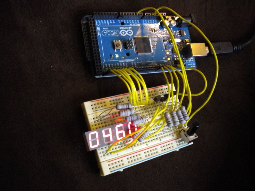
Here is some of the Arduino code I wrote:
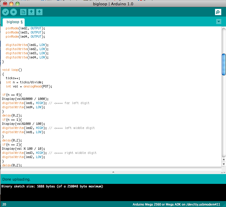
Next step: more displays and configure the senders. They are all just variable resistors so they should work just like the pot. Like I said I might have to use an OP amp or a voltage divider to get a nice input but it shouldn't be too bad.
The only problem I'm running into is that some of the "off" led's are faintly on when they should be completely off. I can't tell if this has something to do with the delays in the code or if my resistors are storing a minuscule amount of current. They are big metal oxide resistors, I thought I had ordered smaller wattage ones.
Henry
Posted: May 02, 2012 12:57 AM
by Xenocide
Looking good man, looks like you're almost ready to start gathering data on the inputs (min/max readings for various temps, etc.) Double check that you don't reset the numbers to zero somewhere. Do the extra segments light up no matter what the other numbers are? If they only glow if the other numbers show them add a slightly longer delay.
Posted: May 04, 2012 2:43 PM
by mooseheadm5
Posted: May 04, 2012 3:24 PM
by Xenocide
$24 to have the extra buttons and not have to do all that wiring? Yes please. The uno has like 6 analog ins, should be enough. It's a TOTALLY different system, but it's a much easier environment. I could even do a little board that'd fit into the OBC enclosure and put the keypad on the I2C bus. I just don't know about that display. Sort of looks like it'd be hard to read. It'd be easy to replace though. I think I'll pick one of these guys up soon.
Re:
Posted: Jun 21, 2015 1:09 AM
by tig
Xenocide wrote:$24 to have the extra buttons and not have to do all that wiring? Yes please. The uno has like 6 analog ins, should be enough. It's a TOTALLY different system, but it's a much easier environment. I could even do a little board that'd fit into the OBC enclosure and put the keypad on the I2C bus. I just don't know about that display. Sort of looks like it'd be hard to read. It'd be easy to replace though. I think I'll pick one of these guys up soon.
Bump. Because I want to do the same thing.
Did you ever make any progress on this?
Re: Rectangular aftermarket gauges?
Posted: Jun 21, 2015 2:46 AM
by dcains
There's already a myE28 and BigCoupe group buy going on for a digital oil pressure and oil temp gauge board (fits inside the cluster) going on, although I believe all have been sold.
Here's a link to the original page:
http://www.claasi.de/tip001400.php
Here's the group buy thread:
http://www.mye28.com/viewtopic.php?f=4&t=131799
And, if you want a voltmeter and/or fuel/air ratio gauge (installs near radio):
http://www.mye28.com/viewtopic.php?f=4&t=87588
Re: Rectangular aftermarket gauges?
Posted: Jun 21, 2015 3:05 AM
by tig
I'm already in on the digital oil gauge. I wanted to know if @Xenocide had made progress on his project.
Re: Rectangular aftermarket gauges?
Posted: Jun 22, 2015 12:59 PM
by Tinkwithanr
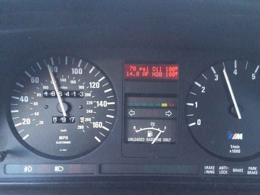
I've actually been working on a display that would fit into the stock water temp location and give 4 readings of whatever you want. It's pretty straight forward, along the lines of what others have done in the thread already with an arduino and the 16x2 display. Right now I'm having some issues with the screen driver reliability, but once I get that ironed out I want to offer the whole system as a kit that is more or less plug and play. One thing I like about this display is how closely it matches every other display in the car, It looks like it could have come this way from the factory. I really don't want to add a bunch of modern 52mm gauges to the interior.
I've also found a full rectangular lcd (480x800 res) that would replace the entire center gauges (fuel level, water temp, turn signal and service indicator), but haven't had time to build up the software to drive it yet. It would probably require a raspberry pi to run it (as opposed to arduino), but the options of what could be displayed are increased greatly.
Here's my install as of now (sorry for the potato phone pic). It's got Oil pressure, Oil Temp, AFR and Water Temp:
Re: Rectangular aftermarket gauges?
Posted: Jun 22, 2015 1:13 PM
by tig
Tinkwithanr wrote:I've actually been working on a display that would fit into the stock water temp location and give 4 readings of whatever you want. It's pretty straight forward, along the lines of what others have done in the thread already with an arduino and the 16x2 display. Right now I'm having some issues with the screen driver reliability, but once I get that ironed out I want to offer the whole system as a kit that is more or less plug and play. One thing I like about this display is how closely it matches every other display in the car, It looks like it could have come this way from the factory. I really don't want to add a bunch of modern 52mm gauges to the interior.
I've also found a full rectangular lcd (480x800 res) that would replace the entire center gauges (fuel level, water temp, turn signal and service indicator), but haven't had time to build up the software to drive it yet. It would probably require a raspberry pi to run it (as opposed to arduino), but the options of what could be displayed are increased greatly.
Here's my install as of now (sorry for the potato phone pic). It's got Oil pressure, Oil Temp, AFR and Water Temp:


Please share details when you can!
Re: Rectangular aftermarket gauges?
Posted: Jun 22, 2015 2:07 PM
by dcains
Wow, that's pretty damn cool.
Re: Rectangular aftermarket gauges?
Posted: Jun 22, 2015 3:06 PM
by trevmmeister
Tinkwithanr wrote:I've actually been working on a display that would fit into the stock water temp location and give 4 readings of whatever you want. It's pretty straight forward, along the lines of what others have done in the thread already with an arduino and the 16x2 display. Right now I'm having some issues with the screen driver reliability, but once I get that ironed out I want to offer the whole system as a kit that is more or less plug and play. One thing I like about this display is how closely it matches every other display in the car, It looks like it could have come this way from the factory. I really don't want to add a bunch of modern 52mm gauges to the interior.
I've also found a full rectangular lcd (480x800 res) that would replace the entire center gauges (fuel level, water temp, turn signal and service indicator), but haven't had time to build up the software to drive it yet. It would probably require a raspberry pi to run it (as opposed to arduino), but the options of what could be displayed are increased greatly.
Here's my install as of now (sorry for the potato phone pic). It's got Oil pressure, Oil Temp, AFR and Water Temp:

That 480x800 center screen would honestly be one of the coolest things ever. If one were to program it to emulate the original facade of the cluster, yet with oil temp, oil pressure, coolant temp, fuel level, and blinkers, I would totally be down for buying whatever it took to make it work.
