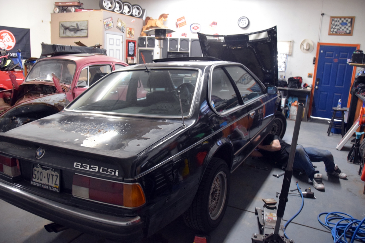
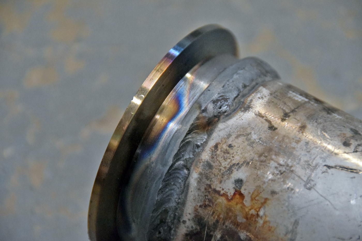
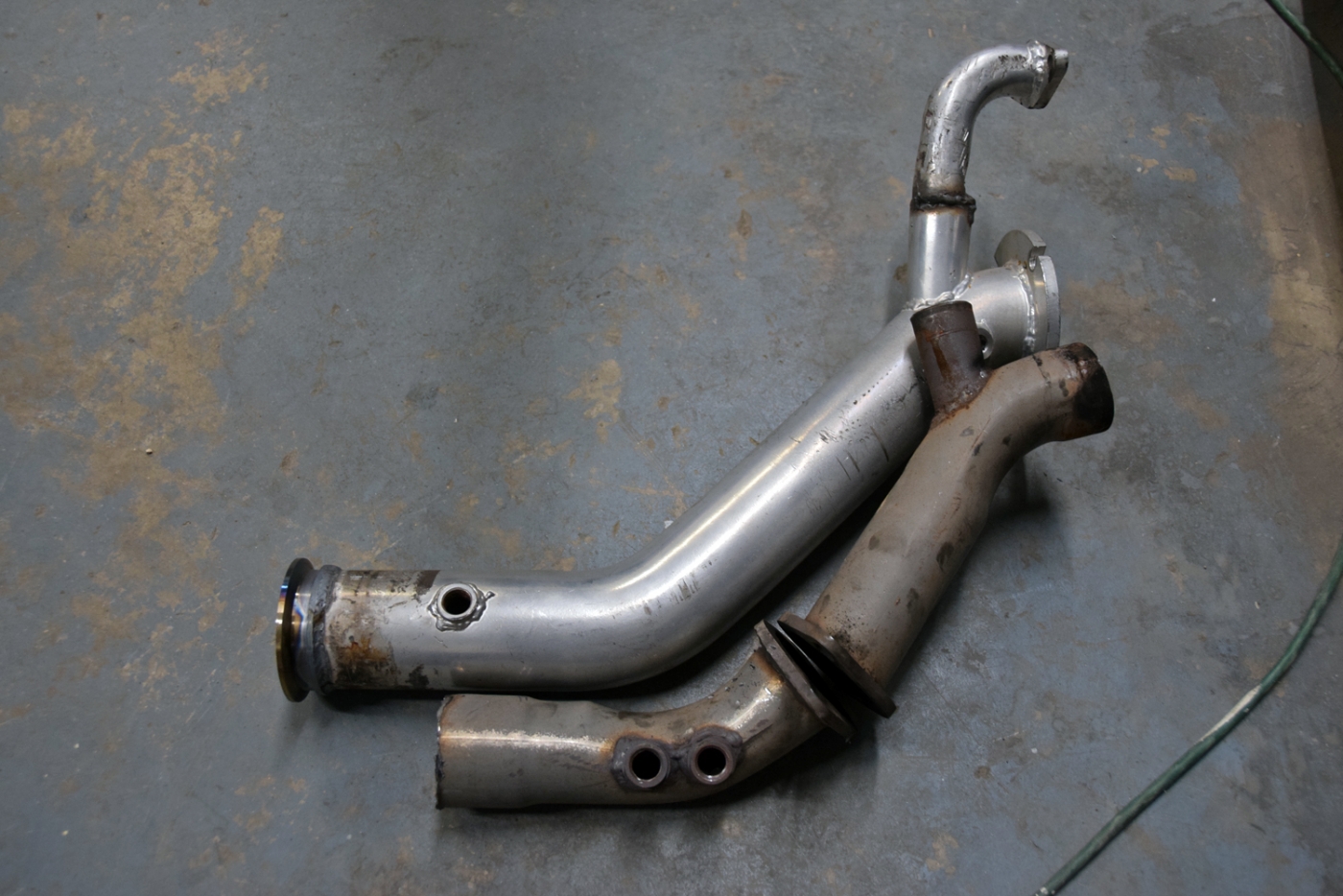
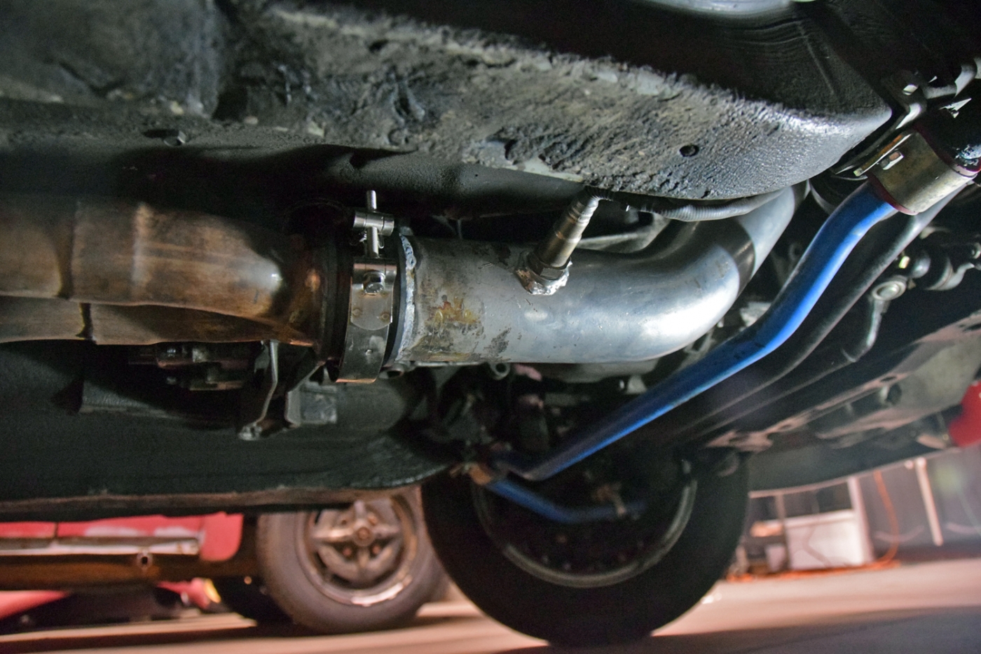
All my parts arrived so I was able to make some progress today!
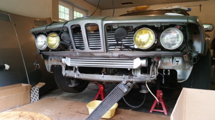
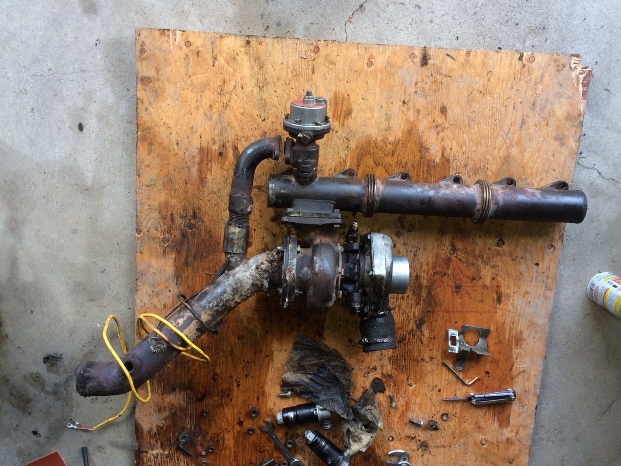
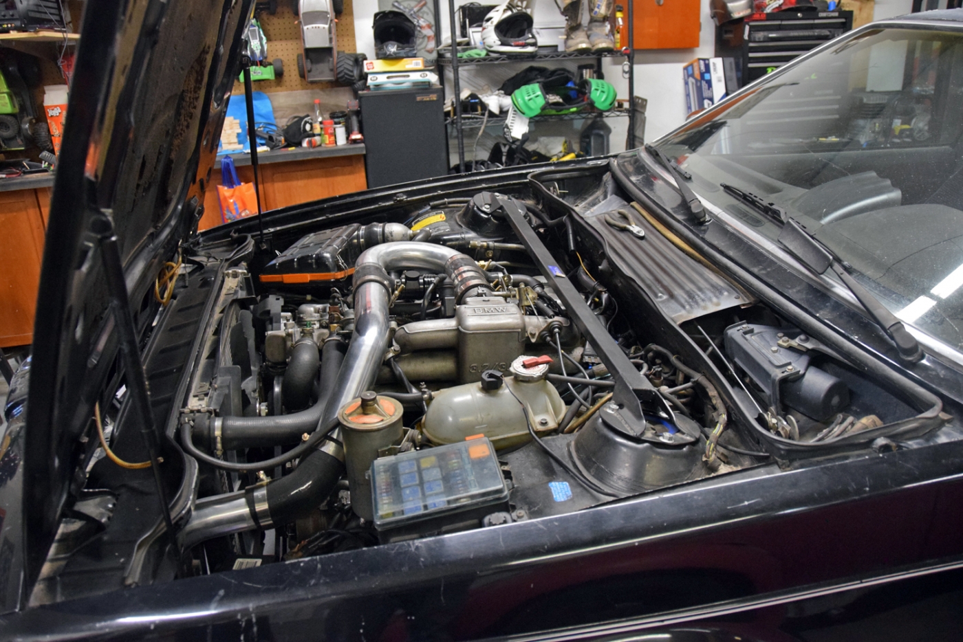
First, the setup without the intercooler:
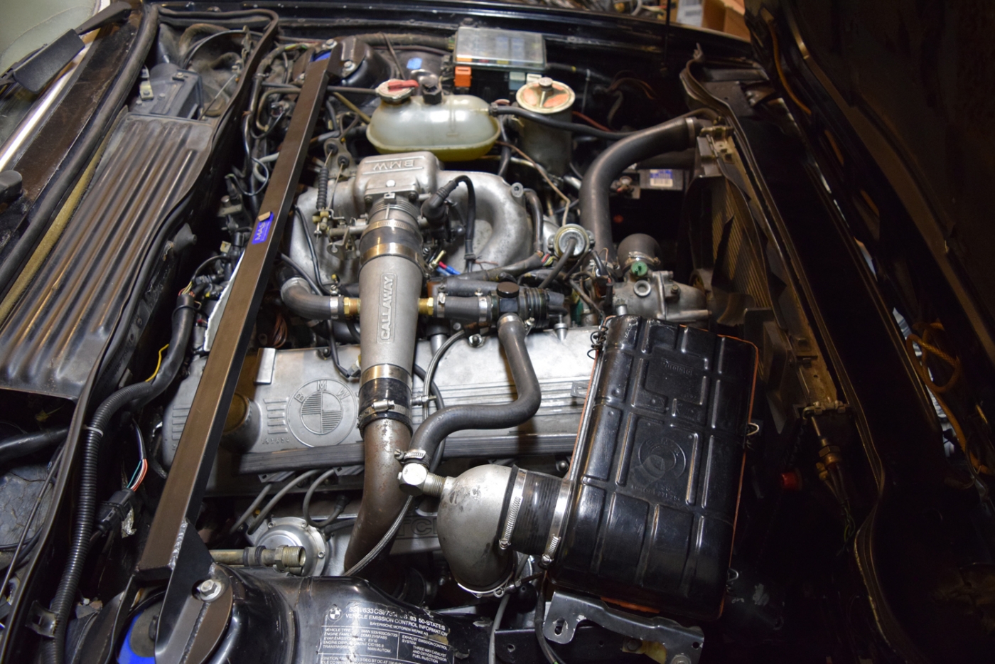
I had been investigating intercoolers and read a lot of theory but a few things really stood out.
-It should be sized to the flow requirements of the engine...
-Get the unit with the least amount of pressure drop (and most amount of flow)
-Place in area of turbulent air flow for maximum efficiency
-Air to air is really more efficient at the track. Water/air is arguably better for street use.
-Too big of an intercooler may simply take more time for you to reach boost threshold than the appropriate unit.
However, for track application, you need the largest intercooler possible to be able to dissipate heat after continued hard use. The larger the surface area, the better. Core depth isn't really critical as the deeper you get, there are diminishing returns and added weight.
A great read here if you wanted a bit more detail than Corky Bell's book:
https://www.mishimoto.com/engineering/2 ... selection/
Before I explain what size I selected, I did some reading about charge piping size. Basically, you size similar to the intercooler, as small as possible that will allow the CFM flow requirement. Bends and kinks will add pressure drop and make your system inefficient. As the airflow travels through a smaller diameter pipe, it will speed up. This is fine until the air travels up to a speed around mach ~.4. At these speeds, the total flow really becomes limited. So if the air flow rate approaches even .35 it is time to start thinking about upsizing intercooler piping.
My old setup used 2" piping. According to a few sources this pipe size is (street) rated for ~350hp and ~550CFM.
So for the street, this setup is probably close to the ideal size for use at my airflow levels (~380-400CFM).
2.5" piping: rated for ~575hp and 875CFM!
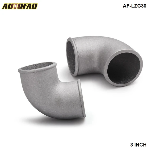
3" piping: rated for ~850hm and 1250CFM!
It also turns out that the compressor outlet is 2". So I elected to keep this 2".
Another suggestion is to increase pipe size as it steps past the intercooler. The idea is that the step minimizes as much pressure drop as possible post intercooler. I had 2.5" piping that I wanted to make work as it isn't too big to fit. It should provide slightly less pressure drop through to my intake manifold. The turbo will work a little less and outlet temperatures should be less, again generating an overall more efficient setup.
My previous intercooler was a 20x6.5" core. With the new piping arrangement, I decided I should get a bigger one for hot days (I didn't like the intake temps I had with over 20F or more above ambient).
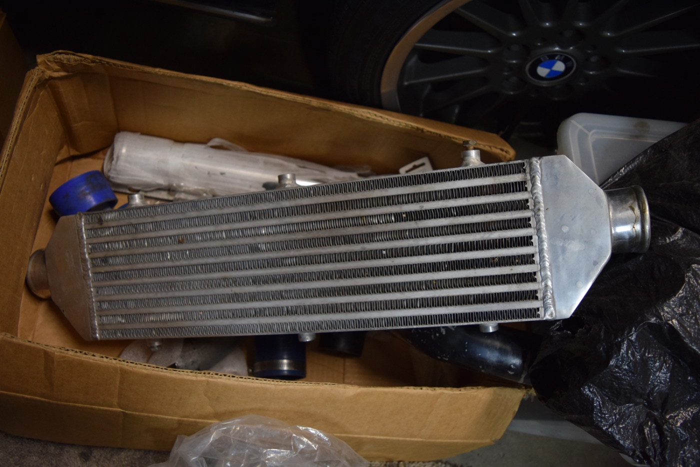
With a new piping layout in mind, I explored intercooler sizes, layouts and placements. Ultimately I decided on an 18x11.5" core manufactured by EMUSA for less than $100 shipped. It is top inlet/out and I flipped this upside down in my head for a pipe routing that I thought would work.
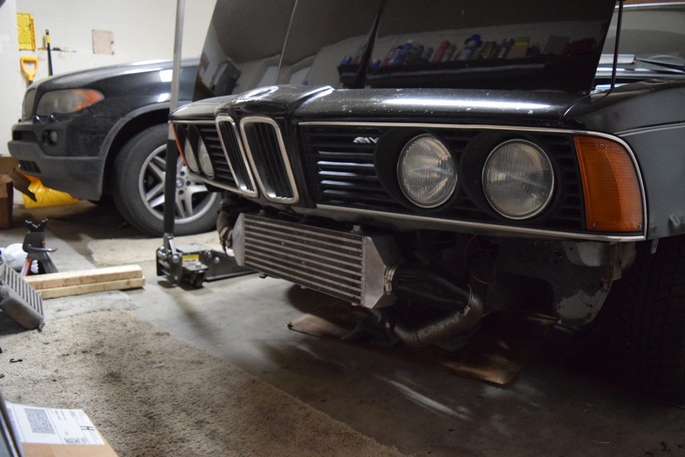
The intercooler was as wide as I could go without modifying the car. It's about 50% larger than the one I had prior. It is placed where the AUX fan used to live, with a total width of 23". This is the size of the radiator cutout and the intercooler lives about 2-3" in front of the radiator. Some horizontal fins ecapsulate the area, so these would have had to be modified to go much bigger.
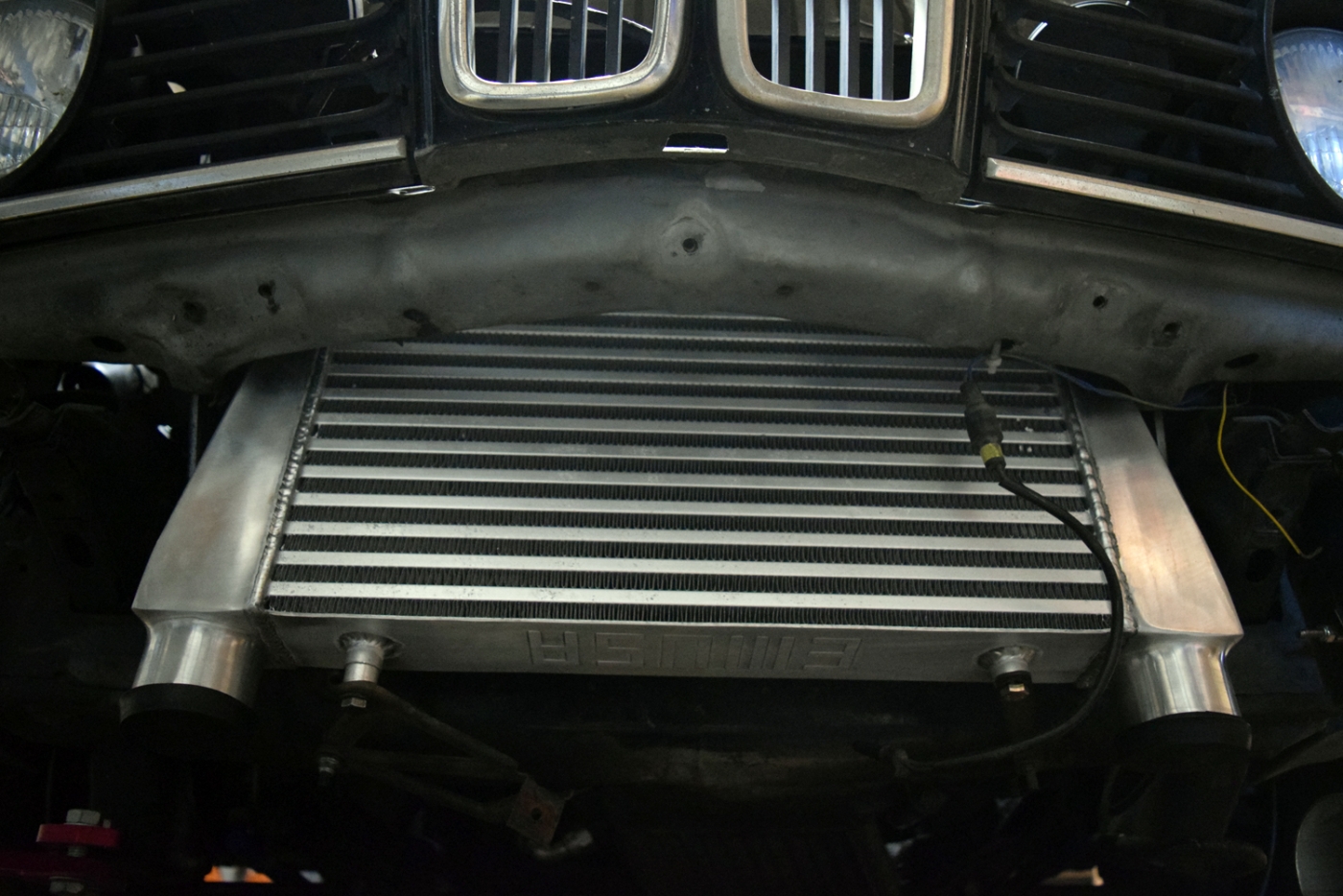
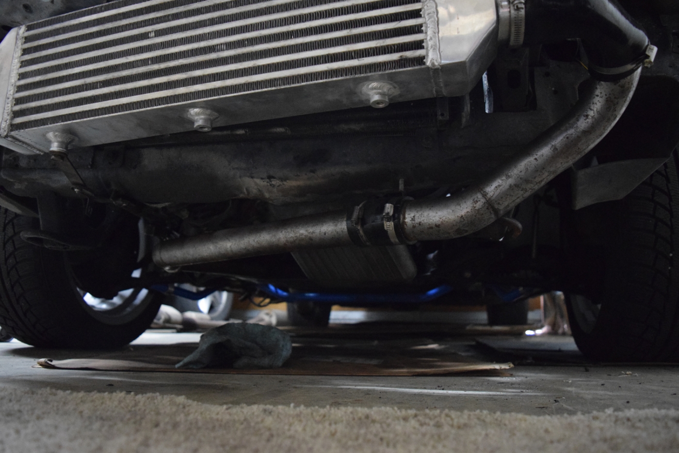
Basically the inlet would come from the engine bay and underneath, or from the headlight opening. With the outlet going up maybe near the headlights. When I tried it out with the intercooler only, it looked like I could make it work.
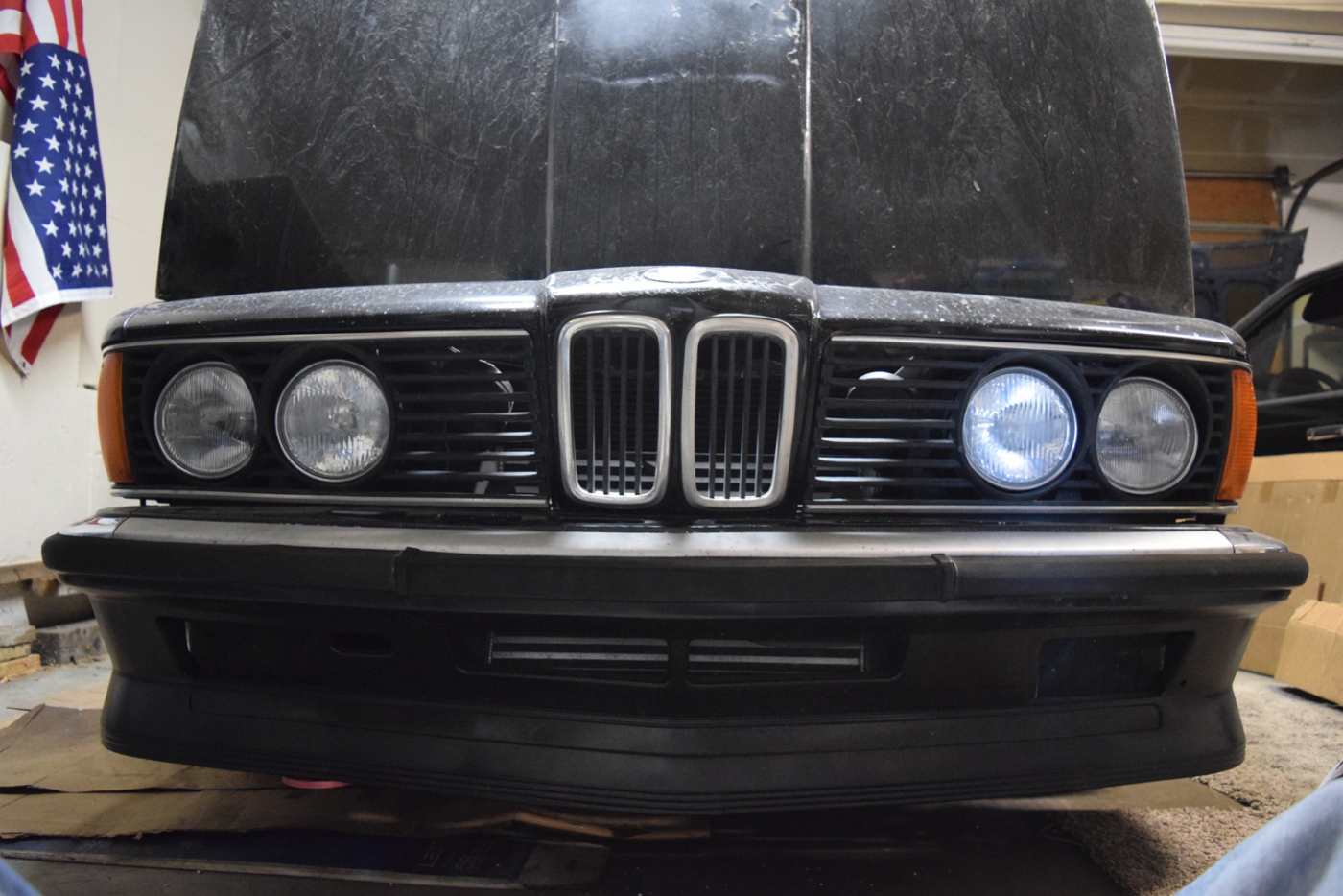
The airdam also had plenty of clearance and fit right up! The openings would be for an oil cooler, but on my car, they are obviously for my intercooler!
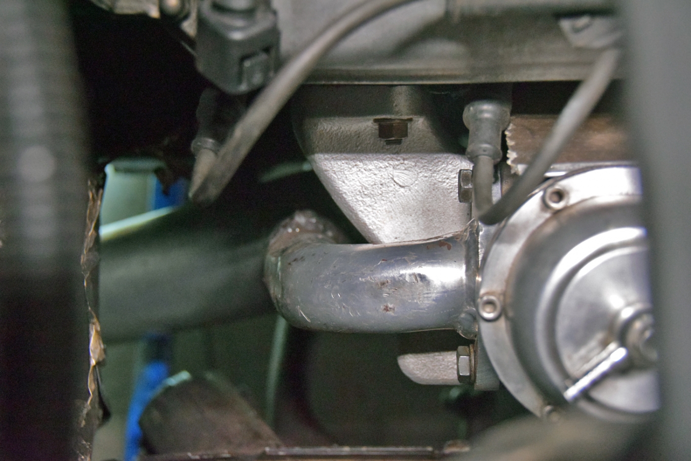
So i checked to see how I could get compressor outlet to fit with the existing air filter setup. Fortunately, this Callaway pipe was close enough to work for me!
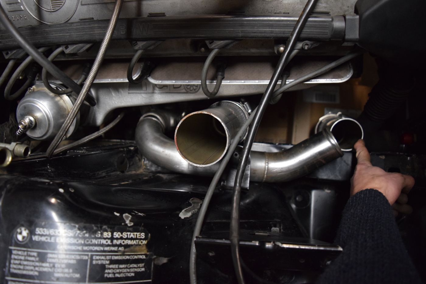
Clearance with the airbox in place and couplers attached.
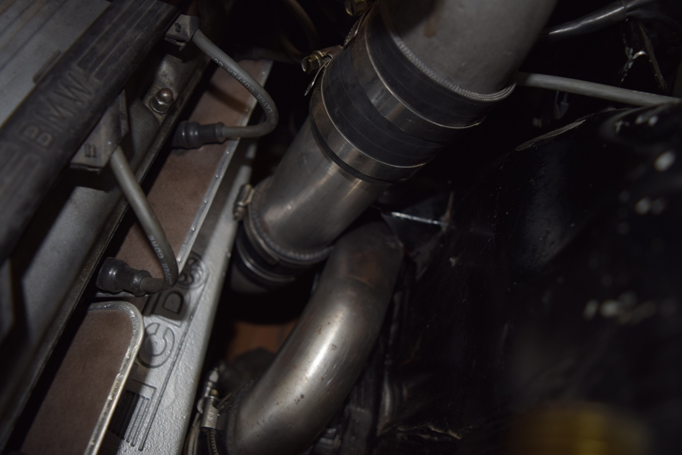
The silicone coupler is a bending reducer opening the pipe to 2.25" gradually as it turns.
There is a 2.25" pipe elbow that bends the air again to be parallel to the ground.
The clearance to the radiator hose is pretty tight, but it isn't touching!
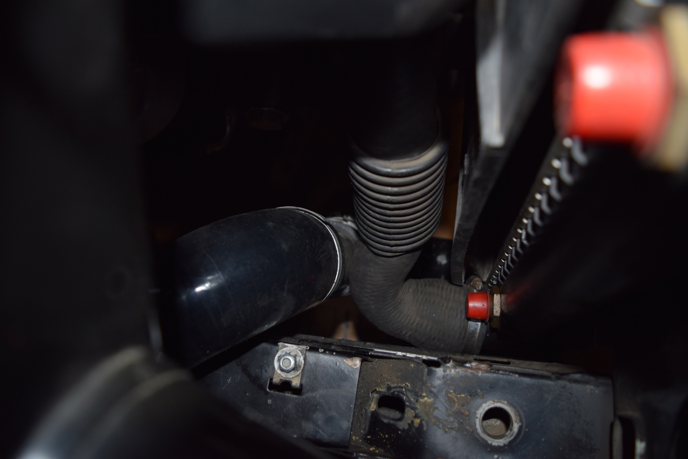
Obviously it comes to the intercooler (it does this in a step to the 2.5" pipe size) and then out and turns up. (I didn't want red, but this was all my supplier had in 2.5" elbows):
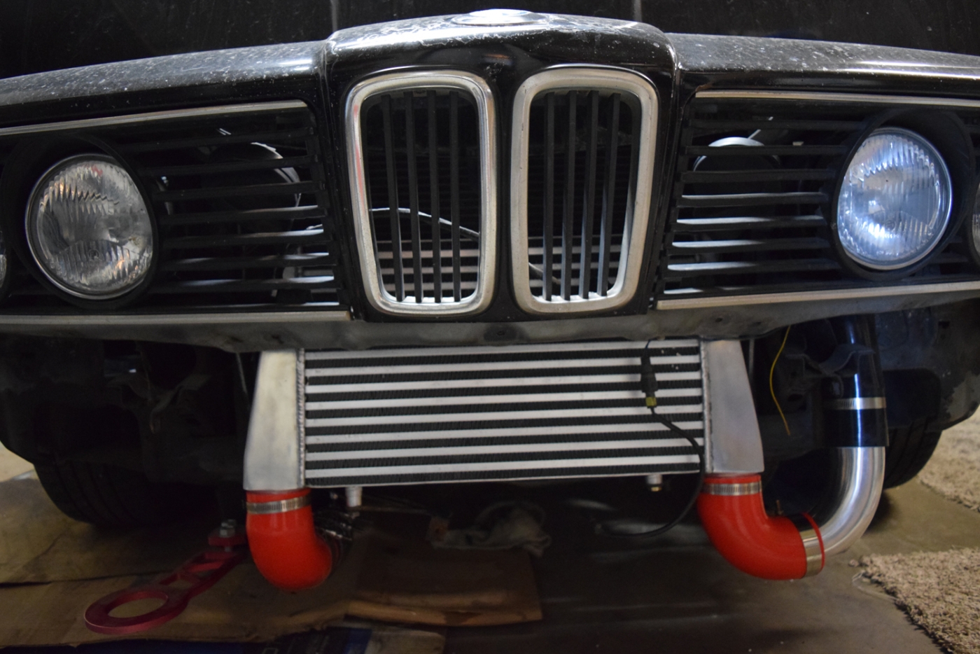
This is where a long silicone coupler brings the air past the headlight mounts and into another elbow into the engine bay.
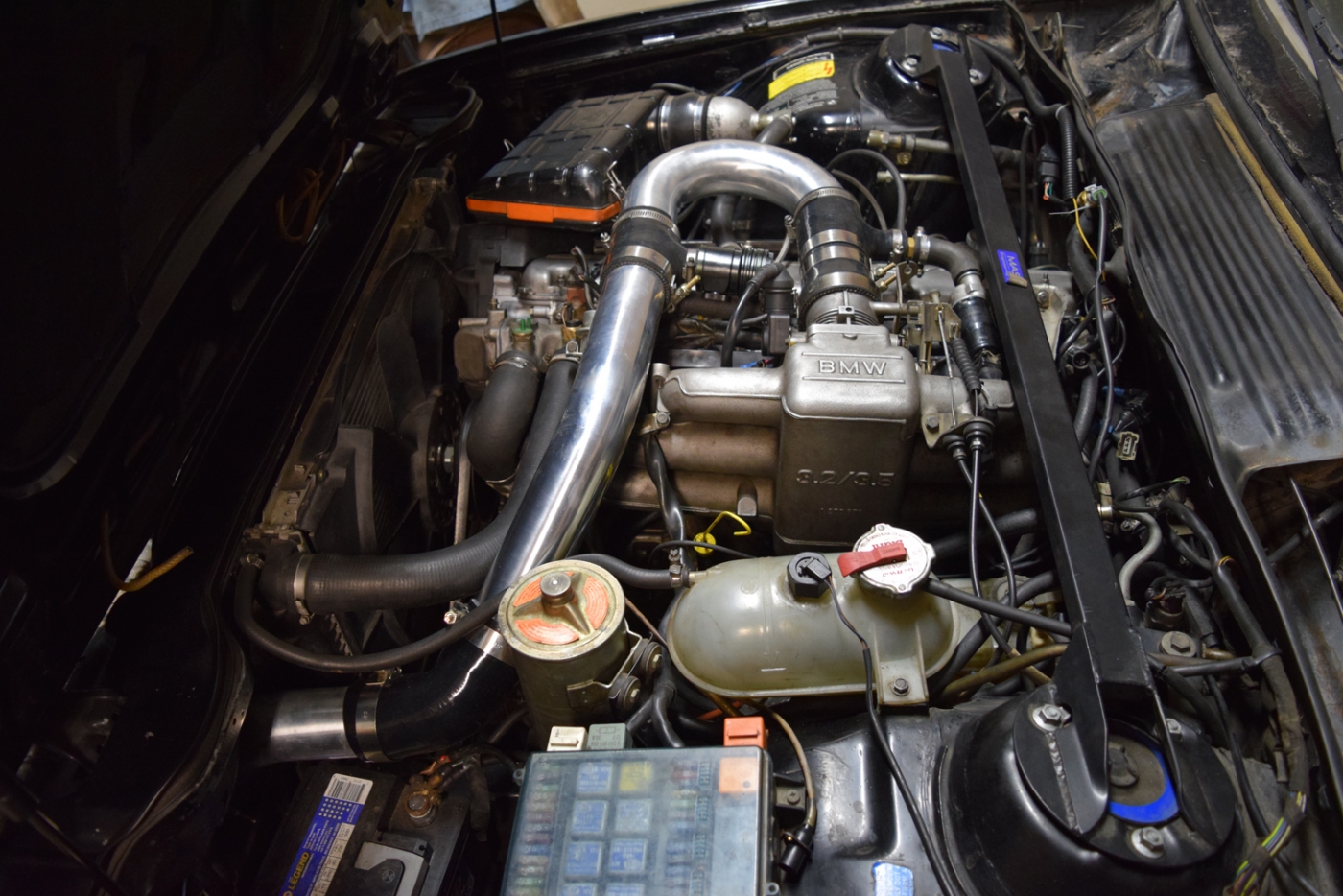
You will notice I am using the same divertor valve as I found the straight coupler with a hose port that would work. I did the same thing for the Idle air pathway as well! There's a step up to the 3" throttle body opening and that's all!
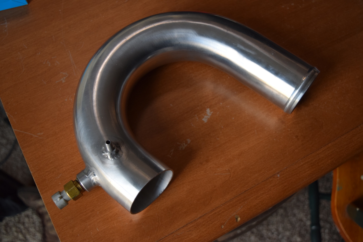
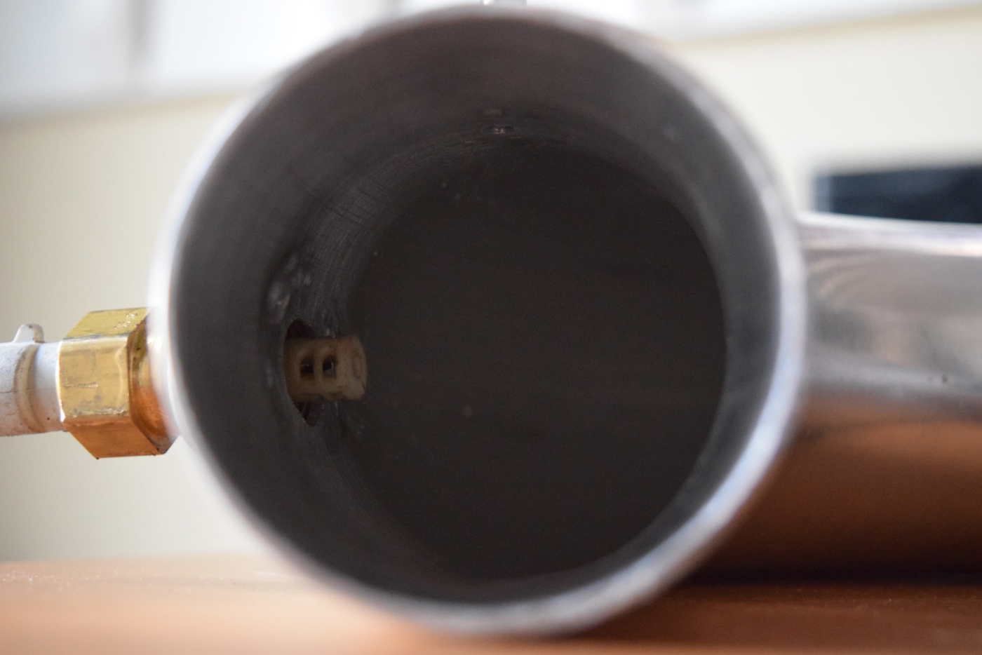
I am going to have a coworker add the AIT sensor on the left end of this 180* pipe, but otherwise that is all that's needed! I had a solution I will probably refine right now that sends diverted air back to the compressor intake, as well as the small amount of blow by that this engine creates.
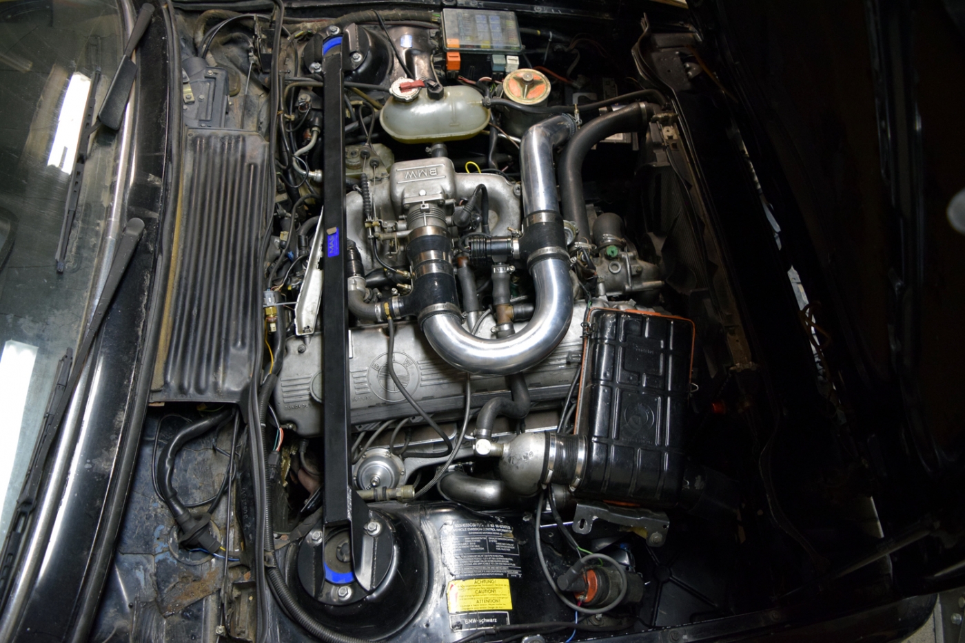
I don't feel like it's super pretty but I think overall it will be quite functional. After a brief test drive, spool doesn't really seem much different than without intercooler piping. Here's the video with the noises inside the car. I still need to finalize the wastegate dump, so this is OPEN with the microphone inside the car:
https://www.youtube.com/watch?v=VXgzQ_6ibo4
More updates to come as weather permits!
