Page 8 of 14
Re: Noob M30B35 Build. 2014-05-24: Engine is out!!!
Posted: Jun 15, 2014 1:04 AM
by DJM1986-5
I knew what you meant but figured I'd add clarification for cek and future reference.
Re: Noob M30B35 Build. 2014-05-24: Engine is out!!!
Posted: Jun 15, 2014 6:58 AM
by trevmmeister
cek wrote: Question: there's a little nipple. show this nipple.
Kyle in NO wrote:The nipple
cek wrote:Thanks Kyle. two small nipples. goes to the nipple. a nipple on each side. the large nipple. 2nd small nipple
DJM1986-5 wrote:one small nipple. other small nipple. vacuum. beating the clock. I plugged the nipple
Guys. Come on. Family-friendly site here. c;
Re: Noob M30B35 Build. 2014-05-24: Engine is out!!!
Posted: Jun 15, 2014 9:27 AM
by tig
I think my flywheel is still at my machinist, who was to check its balance. At least that's what occurred to me at about 3am this morning.
Happy Father's day to all you dads.
Re: Noob M30B35 Build. 2014-05-24: Engine is out!!!
Posted: Jun 15, 2014 11:54 AM
by tig
I have figured out what each coolant hose is for. I think. I'm not as confident on which end goes where though, particularly for the smaller lines that go to the heater and heater control valve. I'm missing the tee (and I don't want to pull it off of Vlad's B34 because those hoses are relatively new and I'd like to leave them intact), so I can't hook everything up today as I had hoped.
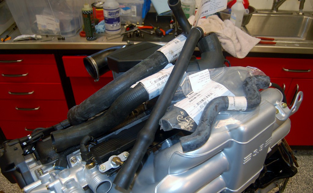
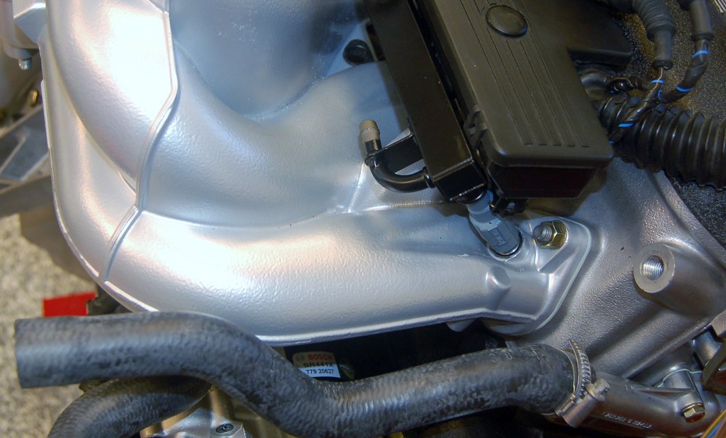
Question: The B35 fuel rail has the fuel inlet facing the front of the engine. How is the fuel line supposed to be routed? Down through the middle space on the intake manifold and then back to the supply? Anyone have a pic of a B35 with this detail showing?
Re: Noob M30B35 Build. 2014-05-24: Engine is out!!!
Posted: Jun 15, 2014 12:03 PM
by tig
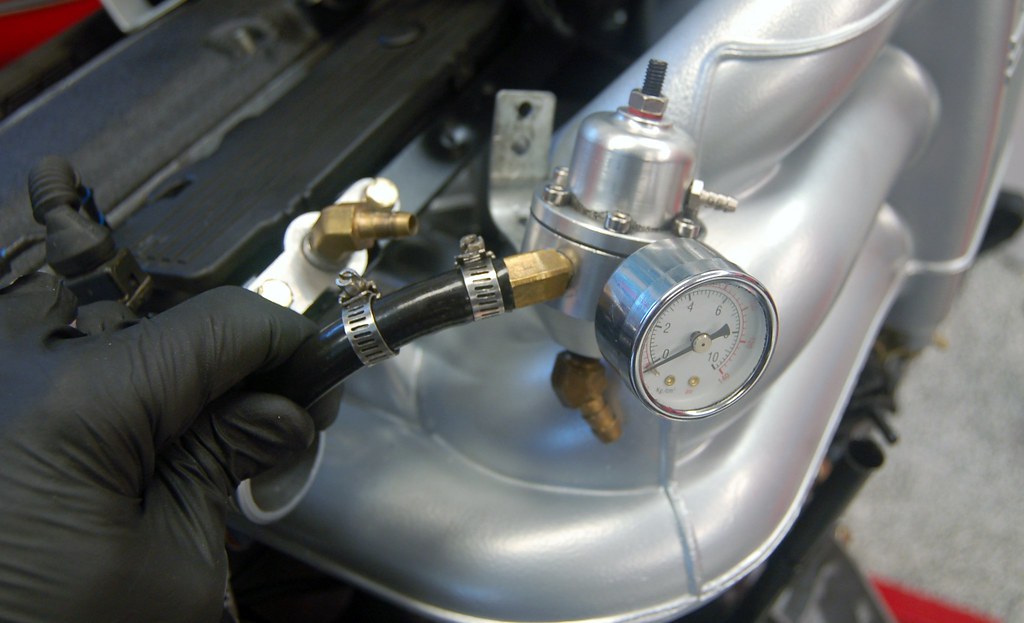
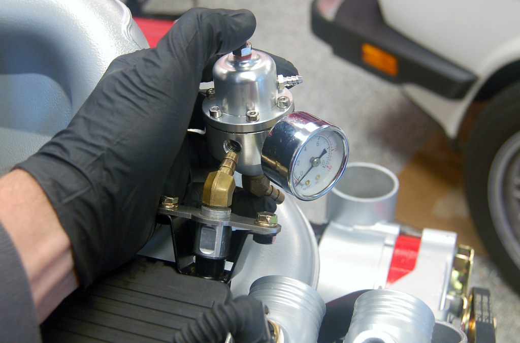
While you all work on answering my previous question, I'm sorting out how to mount my IE AFR.
The B34 intake manifold has some mount points that were sorta convenient. The B35 doesn't.
I'm considering getting rid of the hose between the AFR and the fuel-rail mounty thing and finding some brass fittings that would allow me to just mount it directly. One less hose with clamps to deal with and should be low enough to clear the hood. Good idea? Bad idea?
Re: Noob M30B35 Build. 2014-05-24: Engine is out!!!
Posted: Jun 15, 2014 4:33 PM
by wkohler
Why do you need an adjustable FPR? You're going to run a WAR chip, right?
Re: Noob M30B35 Build. 2014-05-24: Engine is out!!!
Posted: Jun 15, 2014 5:01 PM
by tig
wkohler wrote:Why do you need an adjustable FPR? You're going to run a WAR chip, right?
Maybe. But initially I'm running the stock 179 ECU and AFM. Since this is a high-comp engine with 24lb injectors, Paul Burke recommended that I have an AFPR, at least initially. I also have a wide band gauge (actually two).
Re: Noob M30B35 Build. 2014-05-24: Engine is out!!!
Posted: Jun 15, 2014 5:04 PM
by wkohler
Okay. I've got a friend that had three of those fail before he ditched them and got the war chip, 24# injectors, a stock regulator and a dyno tune. He said the tuning was best money he had spent on the car.
Motor looks great, btw.
Re: Noob M30B35 Build. 2014-05-24: Engine is out!!!
Posted: Jun 15, 2014 6:21 PM
by tig
wkohler wrote:Okay. I've got a friend that had three of those fail before he ditched them and got the war chip, 24# injectors, a stock regulator and a dyno tune. He said the tuning was best money he had spent on the car.
Motor looks great, btw.
As soon as I have it broken in, I'm taking it in for a dyno tune and will likely got with a War chip at that point.
Re: Noob M30B35 Build. 2014-05-24: Engine is out!!!
Posted: Jun 15, 2014 6:26 PM
by tig
I started with the 1/4" neoprene for sound deadening. It doesn't matter that it's not cut perfectly because the Thermo-tec will go over it
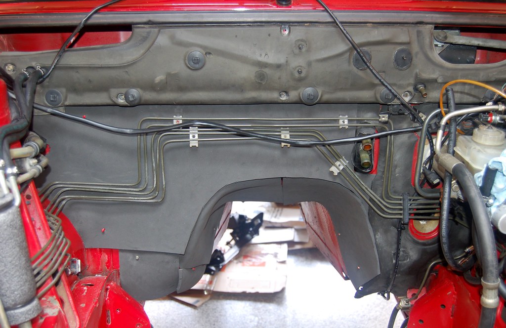
Turned out great!
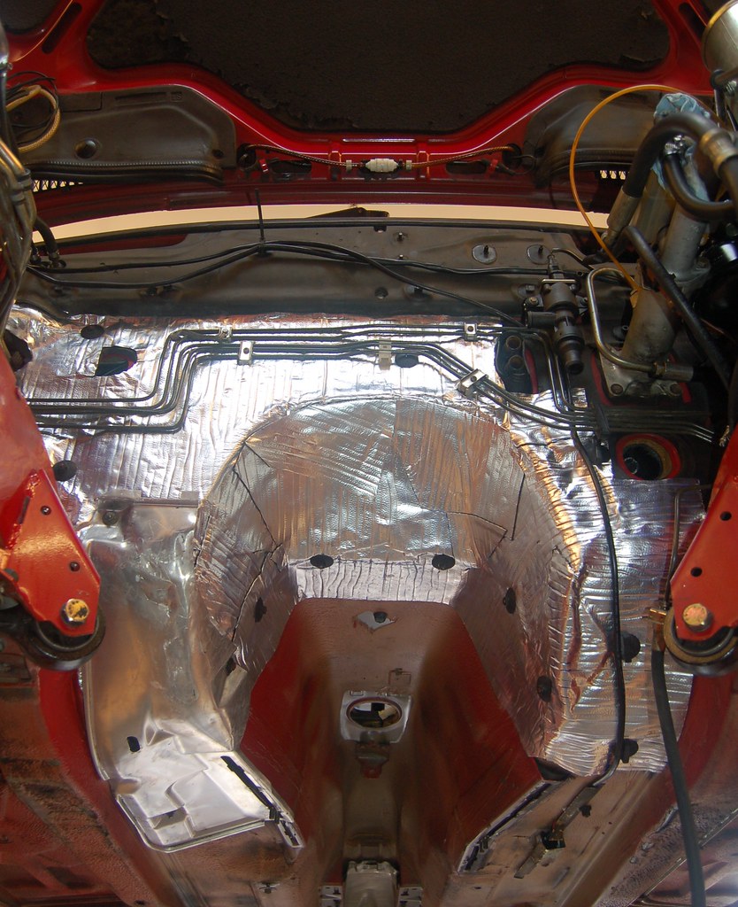
I ended up doing more of the driver's side because....well why not?
The insulation on this fuel cooler thingy was shot. Since I have headers and they get super hot I felt it was worth while replacing the insulation. I started with some pipe insulation...
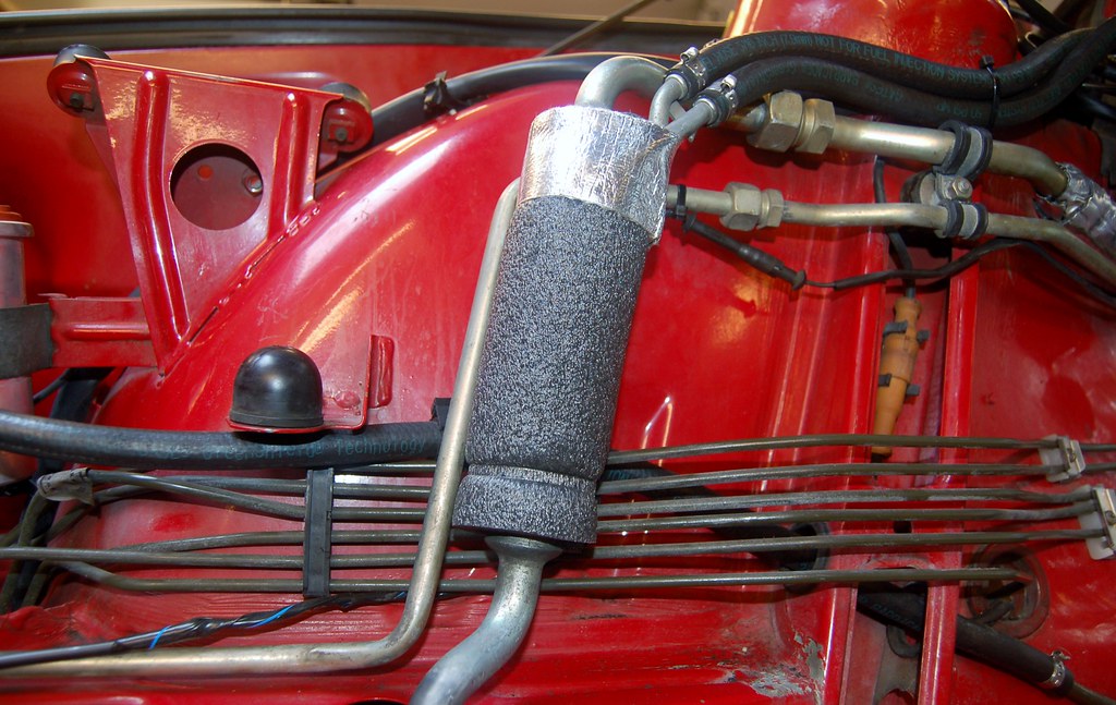
Then wrapped it in Thermo-tec; you can see it blurry on the left of this pic.
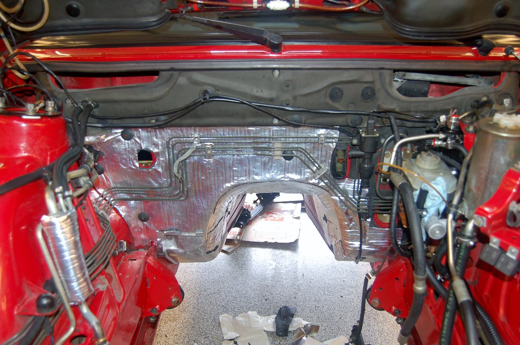
Now the subframe goes back on...
Re: Noob M30B35 Build. 2014-05-24: Engine is out!!!
Posted: Jun 15, 2014 7:14 PM
by tig
Subframe in.
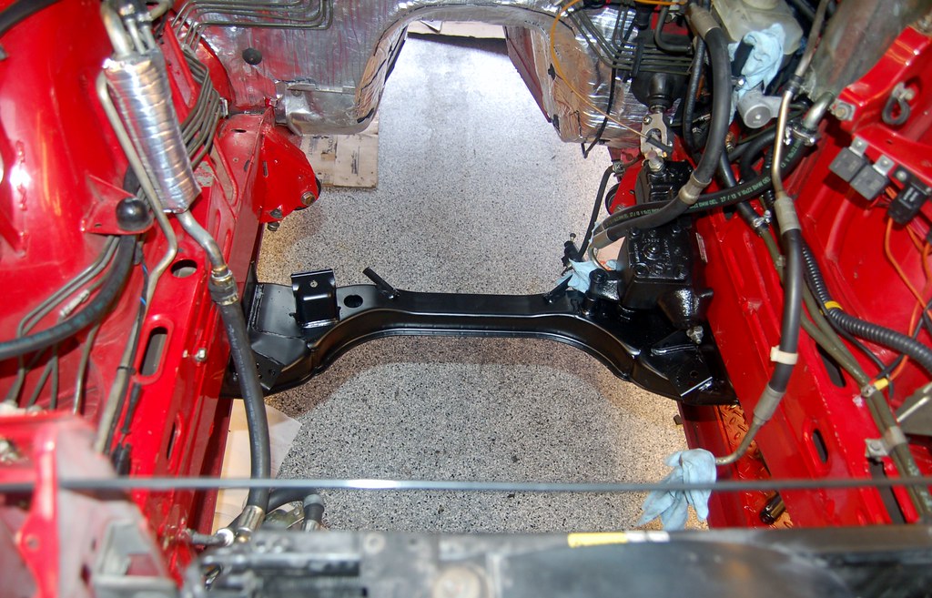
That's all the Father's day Gods will let me get done today, I think. Have to go to a grad party for someone else's kid.
Re: Noob M30B35 Build. 2014-05-24: Engine is out!!!
Posted: Jun 19, 2014 11:15 AM
by tig
Is there anything special or different that needs to be done when adjusting the valves on a brand new head? Just standard cold procedure?
Re: Noob M30B35 Build. 2014-05-24: Engine is out!!!
Posted: Jun 19, 2014 11:38 AM
by Mike W.
cek wrote:Is there anything special or different that needs to be done when adjusting the valves on a brand new head? Just standard cold procedure?
I'm not certain that torquing the head down doesn't change things a bit, so I'd suggest the final adjustment after the head is bolted down tight. Other than that it's the same.
Re: Noob M30B35 Build. 2014-05-24: Engine is out!!!
Posted: Jun 19, 2014 12:33 PM
by pldlnr
I am pretty sure the head gasket comes with instructions on the torque procedures. It will usually includes a final torque after initial start-up and a heat cycle. Adjust the valves before the first start-up and then again after it cools down completely (overnight).
Re: Noob M30B35 Build. 2014-05-24: Engine is out!!!
Posted: Jun 19, 2014 1:36 PM
by Mike W.
pldlnr wrote:I am pretty sure the head gasket comes with instructions on the torque procedures. It will usually includes a final torque after initial start-up and a heat cycle. Adjust the valves before the first start-up and then again after it cools down completely (overnight).
The second adjustment is not necessary IMO, and I've done a bunch.
Re: Noob M30B35 Build. 2014-05-24: Engine is out!!!
Posted: Jun 19, 2014 1:53 PM
by pldlnr
Mike W. wrote:pldlnr wrote:I am pretty sure the head gasket comes with instructions on the torque procedures. It will usually includes a final torque after initial start-up and a heat cycle. Adjust the valves before the first start-up and then again after it cools down completely (overnight).
The second adjustment is not necessary IMO, and I've done a bunch.
You are probably right, Mike. I tend to be a little extra cautious with things like this.
Re: Noob M30B35 Build. 2014-05-24: Engine is out!!!
Posted: Jun 20, 2014 1:40 AM
by tig
Thanks guys.
With the exception of a new CTS and block-off plugs for the t-stat housing, the valve adjustment completes the motor itself. Those parts should be here tomorrow.
My next wrench session will be to re-assemble the steering components. When that's done we'll roll the car into the driveway and drop the engine in and then roll it back onto the lift. I think I need to find a transmission jack for the next step...
I can smell the finish line!
Re: Noob M30B35 Build. 2014-05-24: Engine is out!!!
Posted: Jun 20, 2014 1:55 AM
by tig
Oh, just as I say that, I remember I haven't sorted the C101 connector for the wiring harness yet. I originally was going to do it with the harness separate from the engine, then I realized that I'd likely get the length of something wrong and have to re-do something after it was in the car.
So my plan is to sort out the harness after the engine is set in the car. This will really just be a matter of routing the relay wires from where they currently are near the ECU to where they should be at the fusebox. I am going wire the C101 pig-tail I have from my donor M30B34 directly to the new harness and not use an intermediate 20X connector. I'll wrap it all nice and purdy using F4 tape. It'll be a little tedious doing this while the engine's in the car, but I really want to make sure everything fits since I've never done this before. Maybe I'm just being paranoid and I should just do it while it's out of the car.
Other things I know I have to do:
- Connect cooling hoses and put radiator back in.
- Figure out how I'm going to mount the B35 coil.
- Attach headers. May do this before I drop engine in. I bought 35mm studs so it will be slightly easier to do than before either way.
- Figure out how to secure the B35 air filter housing. I may wait to do this and just use my newly powder coated B34 housing initially. I really do want the cleaner looking B35 housing in there in the end though.
- Drop in the new in-tank fuel pump.
- Install short-shift kit.
- Install lightened & balanced flywheel and new clutch.
- Install rebuilt driveshaft.
- Reinstall exhaust. (once the car is drivable I'm taking it into a shop and having the exhaust rebuilt)
- Fill fluids. Bleed brakes, PS, clutch.
- Remember to tighten steering column nut (I have a piece of tape on the dashboard where I wrote "don't forget steering nut!").
- Cross fingers and start it up. 20 minutes, then re-torque head bolts.
I'm sure there's more. It's time I start really driving a punch list though. Any help you guys can give in flushing it out greatly appreciated.
Re: Noob M30B35 Build. 2014-05-24: Engine is out!!!
Posted: Jun 21, 2014 1:36 PM
by tig
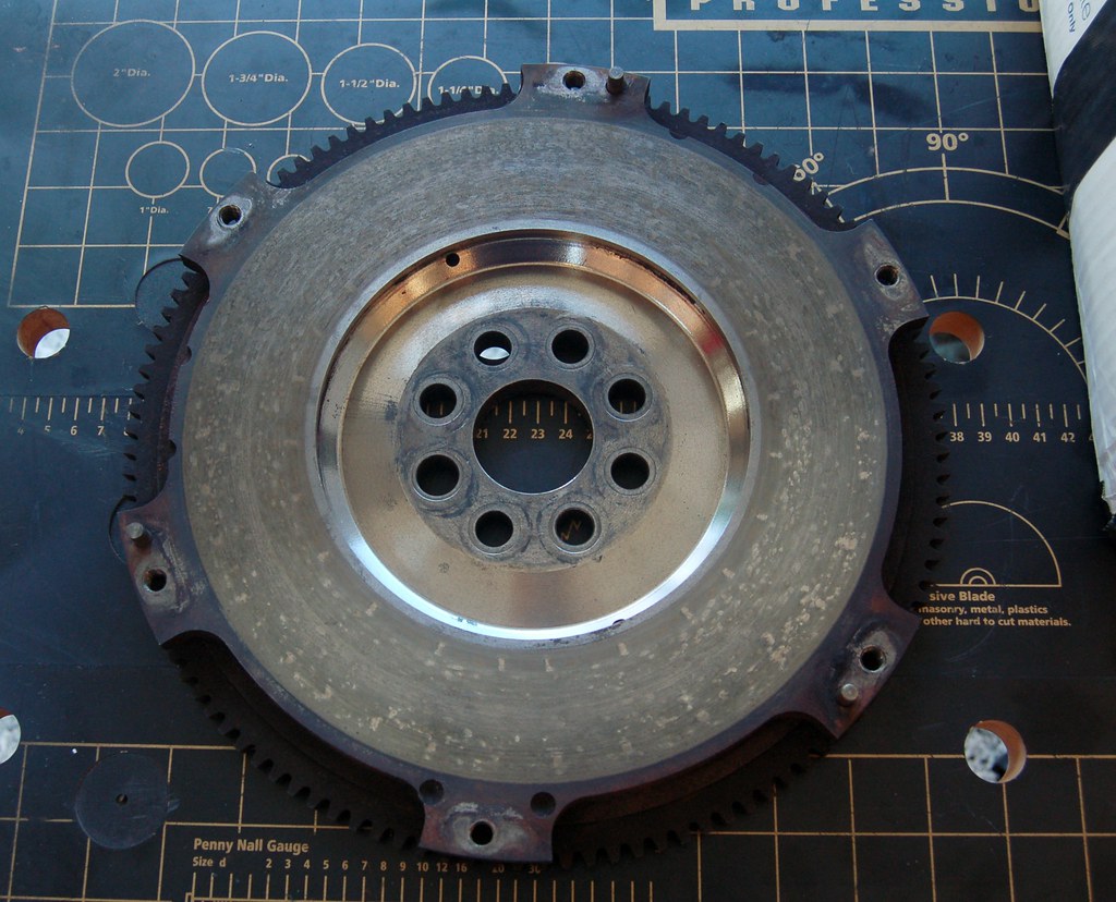
I know you all were wondering if I'd ever find my flywheel.
Well I did.
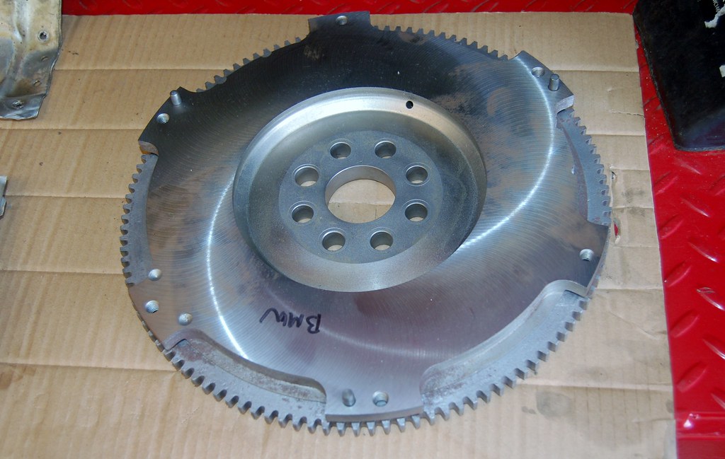
It was at the machinists...
Re: Noob M30B35 Build. 2014-05-24: Engine is out!!!
Posted: Jun 21, 2014 9:14 PM
by tig
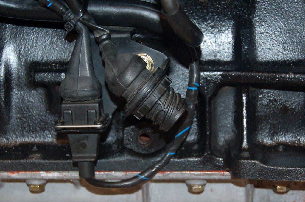
This is for a B35 O2 sensor, right?
Re: Noob M30B35 Build. 2014-05-24: Engine is out!!!
Posted: Jun 21, 2014 10:39 PM
by Ron535i
cek wrote:This is for a B35 O2 sensor, right?
Correct.
Re: Noob M30B35 Build. 2014-05-24: Engine is out!!!
Posted: Jun 21, 2014 10:59 PM
by ldsbeaker
cek wrote:I know you all were wondering if I'd ever find my flywheel.
Well I did.

It was at the machinists...
How much did they lighten that forya? (Final weight?)
Re: Noob M30B35 Build. 2014-06-21: Wiring harness fight!!!
Posted: Jun 22, 2014 1:32 AM
by tig
The flywheel is 17lbs.
I spent almost all day fighting with the wiring harness. I realized that there were two ways I could do it: 1) Just blindly follow the FAQ and cut & splice quickly or 2) Make sure every wire was done correctly and that I understood what went where.
I'm glad I took my time because I've learned a ton. I still have some questions, but it's slowly going together.
Here's where I started. On the bottom right is the C101 pig-tail from the donor B34.
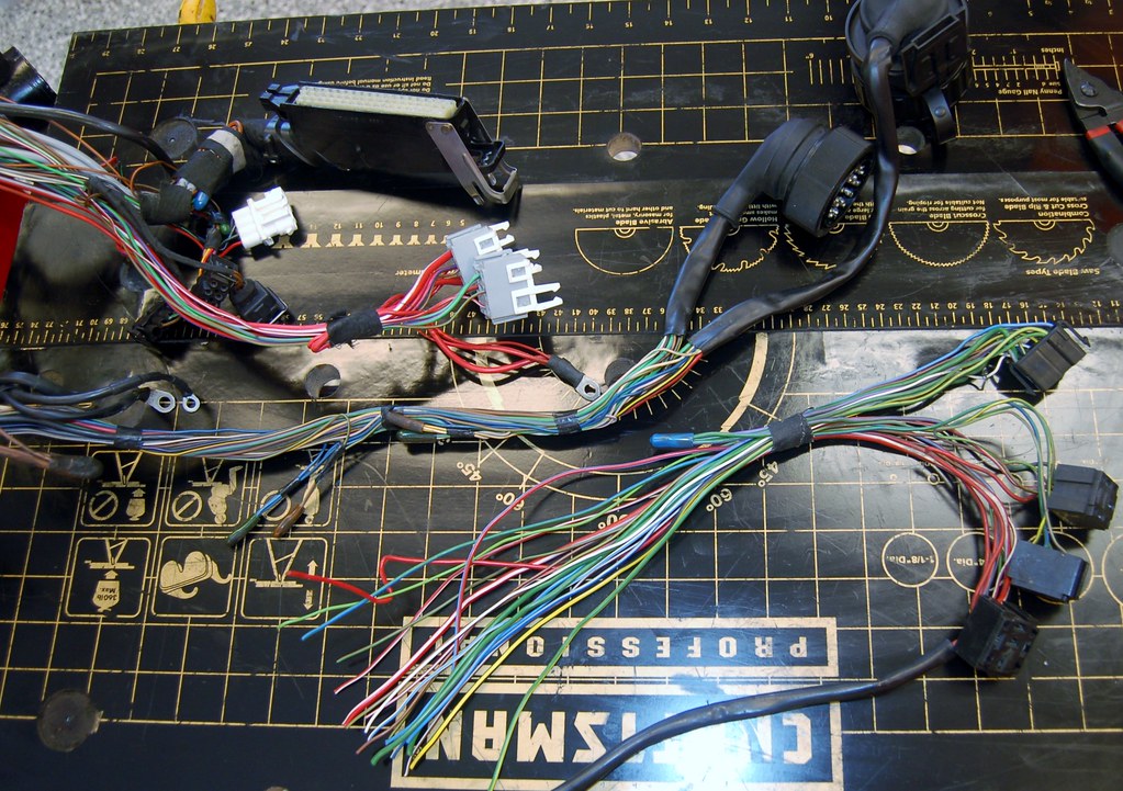
This is C103 by the glove box. The engine speed sensor (small black wire) in harness needs to go to pin 1. The White/Black wire from the harness goes to Pin 3. Pin 4 is from the AC switch and goes to pins 40/41 on the ECU (although I'm still verifying this is absolutely correct). To make this all work, I pulled a male C103 connector from my donor B34 harness and 'upgraded' it with a pin in slot 4.
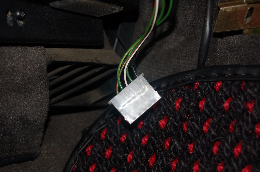
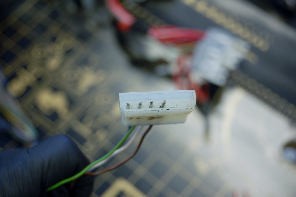
I need to get a B35 O2 sensor plug. I won't need this while I'm running the wideband gauge, but after the rig is tuned, I'll want to go back to stock sensor.

On E32/E34 harnesses the relays are by the ECU, and there's nowhere to mount them securely in the glove box. So I need to re-route those connections to the other end of the harness by the C101. It turns out that the green/violet lines that go to 87 on the fuel pump relay can all be removed from the B35 harness, except the small one that goes through the part above the fuel rail and down to the O2 sensor connector. I re-routed it and spliced it in.
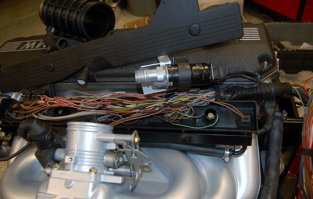
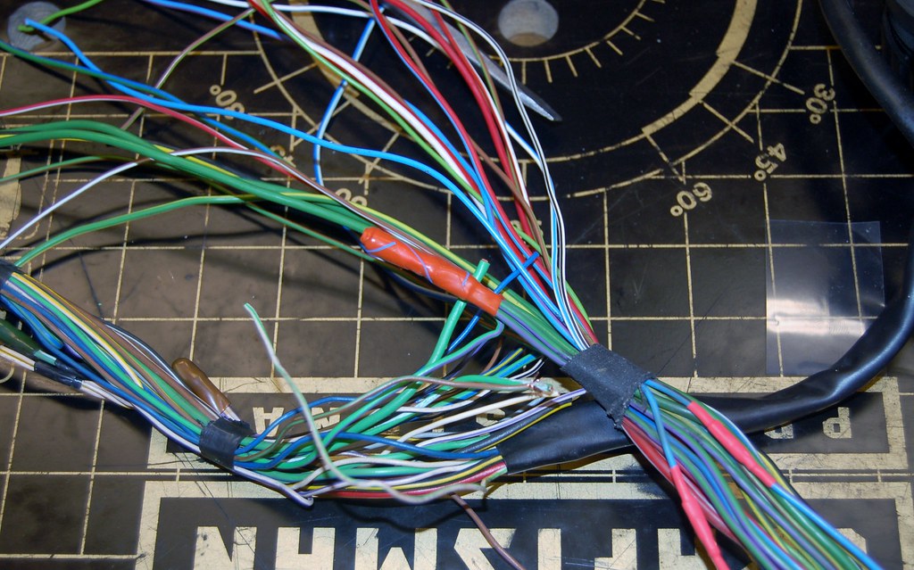
Things should go more quickly now that I've got everything decoded and my confidence in what goes where is up....
Re: Noob M30B35 Build. 2014-06-21: Wiring harness fight!!!
Posted: Jun 22, 2014 6:22 AM
by tig
Fun stuff. Just a few wires left that I'm not quite sure about.
Butt connectors. Rule.
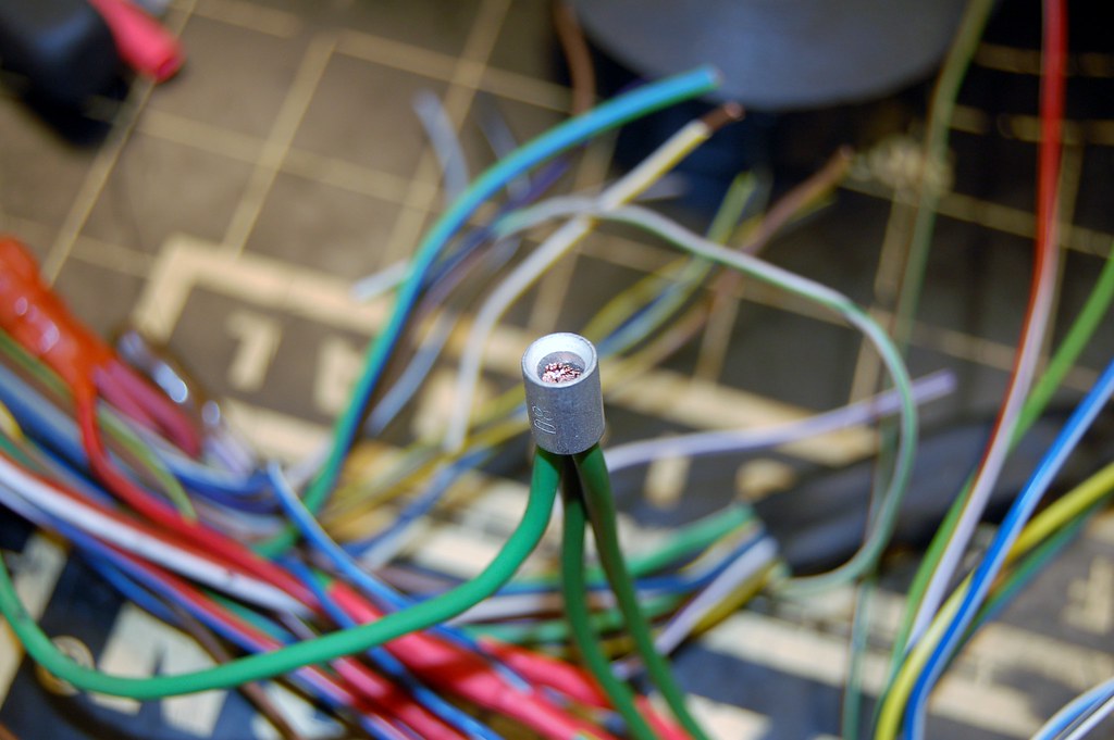
I don't have the nice hard plastic covers BMW used to cover their butt connectors, but seems like F4 tape does a nice job.
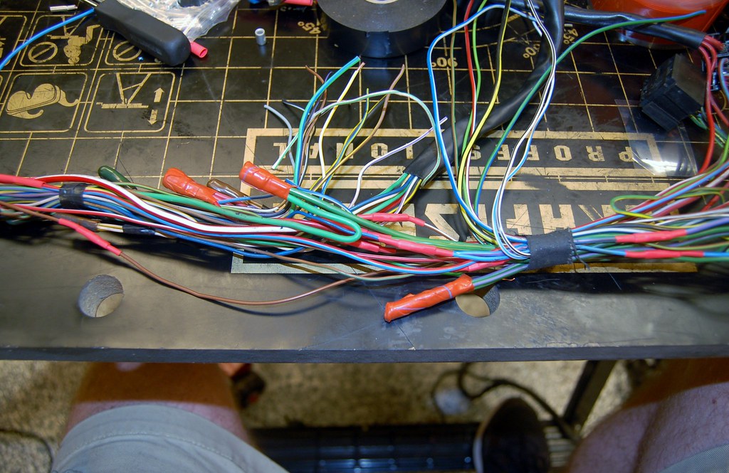
On the bottom right you can see the wires that I'm not sure what to do with. Some are fine, but...
- Green. Comes from 86 on main relay. OBC Relay Box. Seems important. ?!?!?
- Green/Blue. From O2 sensor heater relay. ?!?!?!
On the harness side, I have the black/white that comes from the ECU as "Speed Signal Input". Supposed to go to instrument cluster. But I don't think the E28 speedo has an output. So I think this remains unconnected!?!?
Re: Noob M30B35 Build. 2014-06-21: Wiring harness fight!!!
Posted: Jun 22, 2014 11:25 AM
by BuzzBomb
cek wrote:
On e32/e34 harnesses the relays are by the ECU, and there's nowhere to mount them securely in the glove box.
Fixed
Re: Noob M30B35 Build. 2014-06-21: Wiring harness fight!!!
Posted: Jun 22, 2014 2:42 PM
by Justin_FL
Seems like it would be better to leave the relays so they can be in the glove box, only since there is less tampering on the harness and it is a nicer environment for electrical components. The M5 has two in the glove box near the ECU. I don't particularly remember how they mount and the M5 is surrounded by other cars so I can't open the doors.
Re: Noob M30B35 Build. 2014-06-21: Wiring harness fight!!!
Posted: Jun 22, 2014 2:52 PM
by tig
Justin_FL wrote:Seems like it would be better to leave the relays so they can be in the glove box, only since there is less tampering on the harness and it is a nicer environment for electrical components. The M5 has two in the glove box near the ECU. I don't particularly remember how they mount and the M5 is surrounded by other cars so I can't open the doors.
Way too late for that.

Re: Noob M30B35 Build. 2014-06-21: Wiring harness fight!!!
Posted: Jun 22, 2014 2:54 PM
by tig
BuzzBomb wrote:cek wrote:
On e32/e34 harnesses the relays are by the ECU, and there's nowhere to mount them securely in the glove box.
Fixed
Fixed. Fixed.
Re: Noob M30B35 Build. 2014-06-21: Wiring harness fight!!!
Posted: Jun 23, 2014 3:09 AM
by tig
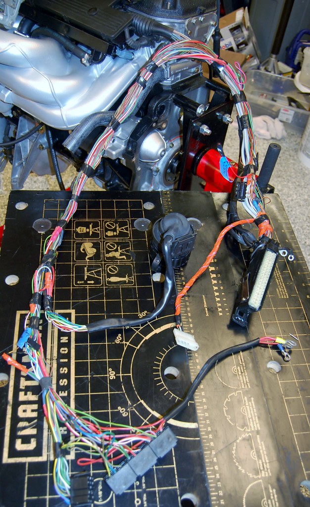
Well, that was much, much harder than I thought it would be. But I got it done.
I want to wait to final-wrap it until it's in the car, I think.
Re: Noob M30B35 Build. 2014-06-23: I beat the wiring harness
Posted: Jun 23, 2014 9:46 AM
by BuzzBomb
Well done. I think this is why most people drop the idea of having a clean install and stuff relays under carpet, etc. The Depot carries the cloth tape to wrap the harness with, which would give it a more factory look, but there are a lot of car restorers and shops that swoop in and buy it all since it's hard to find elsewhere.
Re: Noob M30B35 Build. 2014-06-23: I beat the wiring harness
Posted: Jun 23, 2014 9:49 AM
by tig
BuzzBomb wrote:Well done. I think this is why most people drop the idea of having a clean install and stuff relays under carpet, etc. The Depot carries the cloth tape to wrap the harness with, which would give it a more factory look, but there are a lot of car restorers and shops that swoop in and buy it all since it's hard to find elsewhere.
I'm going to be using F4 tape to wrap it. I have a nice supply of cloth tape, but think the F4 tape will hold up better.
Re: Noob M30B35 Build. 2014-05-24: Engine is out!!!
Posted: Jun 23, 2014 1:29 PM
by tn535i
cek wrote:I know you all were wondering if I'd ever find my flywheel.
Well I did.

It was at the machinists...
It looks nice and shiny but... It looks like it was fly cut on a rotary table ? I didn't think that's how you should do a flywheel and the step for the PP is now gone. Won't that affect the pressure on the friction surface or are you using something different than stock PP and friction disc. Just curious.
It looks like the work you are doing is basically outstanding. We have tried to put that attention to detail in the e30 project my son and I have worked on but we skipped the engine for now and rarely find the time to work on it.
Re: Noob M30B35 Build. 2014-06-23: I beat the wiring harness
Posted: Jun 23, 2014 1:37 PM
by Sportfury70
cek,
This thread is awesome. We never got a chance to get together last time when I needed to do my control arms, but I'm still just right up the road in Kirkland. If you ever need a second person or odd ball tool let me know. Feel free to pm and we can exchange phone #s. I may still have your email too if you prefer that way. God knows theres always work to be done on my car too lol.
Keep up the awesome posting!
-John
Re: Noob M30B35 Build. 2014-06-23: I beat the wiring harness
Posted: Jun 23, 2014 2:10 PM
by tn535i
Kirkland... Hmmm. My 105 yr old grandmother lives in Totem Lake and my aunt in Woodenville. Next time I'm out that way, probably September... and if you don't think it would be too strange of me to ask... IM me a phone number and I'll give you a call. Maybe I could stop by to have a look at the progress and talk BMW's. Always great to meet fellow board members and enthusiasts.
Re: Noob M30B35 Build. 2014-06-23: I beat the wiring harness
Posted: Jun 23, 2014 2:13 PM
by vandiesel
I too love this thread and have the same car teed up and ready. Will start next winter. This motivated me to go all the way with my new 535is
Re: Noob M30B35 Build. 2014-05-24: Engine is out!!!
Posted: Jun 23, 2014 3:08 PM
by tig
tn535i wrote:
It looks nice and shiny but... It looks like it was fly cut on a rotary table ? I didn't think that's how you should do a flywheel and the step for the PP is now gone. Won't that affect the pressure on the friction surface or are you using something different than stock PP and friction disc. Just curious.
I have no freaking idea. This is the first flywheel I've actually ever touched or looked at up close. I bought it off a guy on the forum. From a previous post in this thread:
cek wrote:Bought a flywheel from a guy on the forum here. It came while I was fishing last week.
It was billed as a "early 533/M5 variety". I'm not sure that's what it is, because although it weighs about 17lbs it has tabs on it, where all others I've seen are smooth all the way around.
Did I get mis-led?
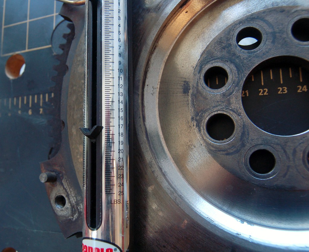
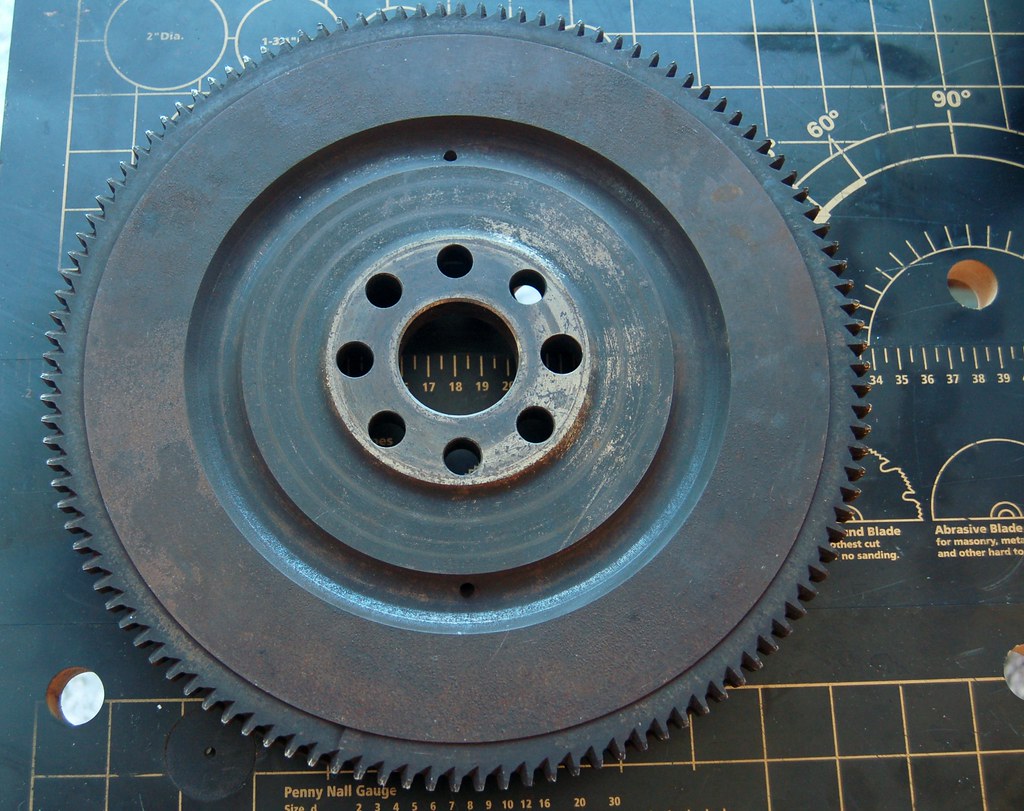
For example, here's pictures from other theads showing a 533 flywheel. Looks totally different:
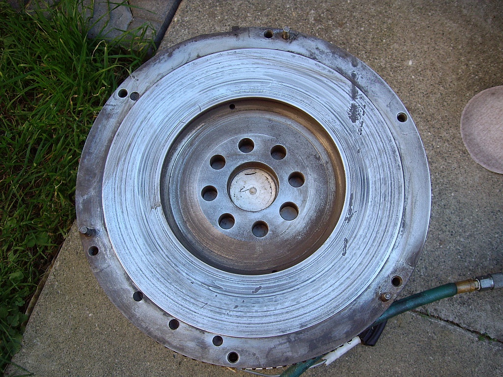
A shameless asshole named Kyle said:
Kyle in NO wrote:I wouldn't touch that flywheel with a 10' pole. It's so incredibly butchered. How do you even know its still balanced properly? I would demand a refund if that junk showed up at my door.
I've since had it balanced. I'm not sure what "step for PP" means.
Maybe I should source another one (or shave the one from Vlad's B34 down?)?
Re: Noob M30B35 Build. 2014-06-23: I beat the wiring harness
Posted: Jun 23, 2014 3:14 PM
by tig
tn535i wrote:Kirkland... Hmmm. My 105 yr old grandmother lives in Totem Lake and my aunt in Woodenville. Next time I'm out that way, probably September... and if you don't think it would be too strange of me to ask... IM me a phone number and I'll give you a call. Maybe I could stop by to have a look at the progress and talk BMW's. Always great to meet fellow board members and enthusiasts.
I actually am in Bellevue. Please do come visit when you are out here. Email me via the forum and we can exchange contact info.
Re: Noob M30B35 Build. 2014-06-23: I beat the wiring harness
Posted: Jun 23, 2014 4:50 PM
by kzolee
For my untrained eye, that flywheel looks properly machined.

Re: Noob M30B35 Build. 2014-05-24: Engine is out!!!
Posted: Jun 23, 2014 6:40 PM
by tn535i
cek wrote:
I'm not sure what "step for PP" means.
If you look at this picture above you'll see the friction surface is proud of the outer ring where the PP is bolted down. There is supposed to be a step there (1/2mm or so, maybe 1mm ?) I'm not sure of the spec but it does decrease the gap between the PP and the flywheel a little and part of the stack up.
I think your flywheel was put on a rotary table under a milling machine to make the cut outs in the OD between bolt locations to lighten it. This has removed a lot of the surface the PP would normally rest on. Is that a problem? IDK but I've seen PP that are not completely flat at the bolt locations but since the whole thing rests on a flat surface if it draws up a little around the bolt who cares. In this case maybe it results in some distortion of the PP so it's not nice and parrallel. But I really don't know if that could be a problem here or not.
In the process of doing what I think was done it may also mean the surface is no longer true to the backside where it mounts to the crank. Again I think because either before or after the cut outs it looks like they used a big fly cutter (think like a lawn mower) to just shave the surface down while they spun the thing around under the cutter with the cutter offset from the center. You should be able to see that. Run your fingernail across the surface and if you can feel it it's a no go. If it feels smooth then bolt it up on the crank and use an indicator to see if it's true when you spin it. Put inward pressure on the Flywheel to be sure it's up against the thrust bearing and rotate a little at a time. Spec might be 0.1mm or about .004" total run out IIRC but I would want it to be about 1/2 that or less. If it's not it's no longer true enough to use without turning it at which point you could put the step back in it and rebalance but still have those gaps.
To be on the page with Kyle it kinda scares me. The proper way to lighten is to put in a lathe and start hogging material out of the backside. Grind the friction surface smooth and also rebalance. This is how we lightened one we did. I'm lucky to have access to a lathe at work and honestly what's been done abbove looks like a lot more work.
Re: Noob M30B35 Build. 2014-06-23: I beat the wiring harness
Posted: Jun 25, 2014 11:51 AM
by unt0uchable
I took the time out of most all of yesterdays work day to read this thread front to back (almost). I hit every page and learned a heck of a lot. It really makes me want to dive into rebuilding one of these just so it can look like your final product. The powder coating, plating, painting; everything looks superb, and I'm sure that OCD personality of yours loves every bit of it.
Keep the updates rolling. It for pretty intense when people were on your ass for wanting to drop the engine out the bottom. Glad that worked out well!
In for moar updates!
Re: Noob M30B35 Build. 2014-06-23: I beat the wiring harness
Posted: Jun 25, 2014 12:40 PM
by Mike W.
tn535i Makes good points as usual, and I thought that picture looked familiar.

Anyway, I agree, it should be stepped, given how a diaphram pressure plate works it may or may not reduce clamping pressure, but it would diminish the effective life of the clutch by the 1 or 2MM of the step. I've also seen flywheels, as in the last one I had surfaced by a machinist I hold in high regard, flycut like this one, but then machined down to reestablish the step. I had no issues with it and was actually using a lighterweight E12/533 clutch in a 535 in order to try to limit pedal pressure in what was then my wife's car.
Re: Noob M30B35 Build. 2014-06-23: I beat the wiring harness
Posted: Jun 25, 2014 12:45 PM
by tig
Given the fear, uncertainty, and doubt I now have about this flywheel, I'm probably going to source another flywheel (or lighten the one I have that's still attached to Vlad's old motor).
FWIW, here's how the PP sits on this flywheel:
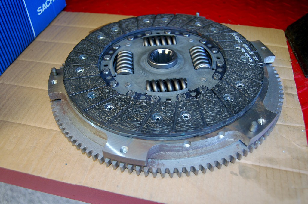
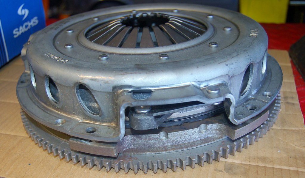
I still am not quite sure what problem you guys are talking about.
Note that my machinist balanced this flywheel and said it was good to go.
Re: Noob M30B35 Build. 2014-06-23: I beat the wiring harness
Posted: Jun 25, 2014 1:26 PM
by Mike W.
I don't think it's a throwaway, it just needs a little more. Stock there is a step, the surface the friction disc rides on is 1-2MM higher than where the pressure plate ears mount. That provides additional preload. It could still be machined in after removing the locating dowels.
On weight it's odd if it's ~17 pounds. That is roughly the weight of a E12 flywheel, without additional machining. 535's are in the 22 range and 533s in the 14.5 area. Since you're going B35 you don't need the motronic tabs would tend to help ID it. Nothing wrong with an E12 flywheel as long as you're M1.1 or 3, not M1.0A.
Re: Noob M30B35 Build. 2014-06-23: I beat the wiring harness
Posted: Jun 25, 2014 1:33 PM
by BuzzBomb
Mike W. wrote:Stock there is a step, the surface the friction disc rides on is 1-2MM Higher than where the pressure plate ears mount.
Fixed.
Re: Noob M30B35 Build. 2014-06-23: I beat the wiring harness
Posted: Jun 25, 2014 3:39 PM
by Mike W.
BuzzBomb wrote:Mike W. wrote:Stock there is a step, the surface the friction disc rides on is 1-2MM Higher than where the pressure plate ears mount.
Fixed.
Correct you are, I misspoke. Corrected.
Re: Noob M30B35 Build. 2014-06-23: I beat the wiring harness
Posted: Jun 25, 2014 4:02 PM
by tig
I just spoke with my machinist and told him about the raised portion. He said he had noticed this and assumed I was using a custom clutch.
He recommends I bring in this flywheel along with the stock one I have and he'll look at them. Option A is to machine down the already lightened one to provide the raised surface. Option B is to lighten the other one and use it. We will decide once he can have them both in hand.
Thanks everyone for being so diligent on my behalf!
Re: Noob M30B35 Build. 2014-06-23: I beat the wiring harness
Posted: Jun 25, 2014 11:42 PM
by trevmmeister
cek did you paint or powder coat your head?
Re: Noob M30B35 Build. 2014-06-23: I beat the wiring harness
Posted: Jun 25, 2014 11:46 PM
by tig
trevmmeister wrote:cek did you paint or powder coat your head?
No, I shaved it.
Re: Noob M30B35 Build. 2014-06-23: I beat the wiring harness
Posted: Jun 25, 2014 11:47 PM
by OcCoupe
My knob is powder coated.
Re: Noob M30B35 Build. 2014-06-23: I beat the wiring harness
Posted: Jun 28, 2014 4:09 PM
by tig
This diagram confuses me.
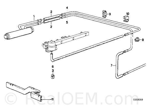
I thought the FPR end of the fuel rail was the "exit". If that's right then the fuel cooler cools the fuel on it's way back to the tank!?


