Auto TPS to Manual TPS Conversion Questions
Posted: Feb 07, 2017 7:10 PM
So in the middle of trying to complete my Front End & Engine Overhaul for the M535i, one of the items was converting the existing Automatic TPS on the Throttle Body to a new Manual TPS.
This was never done when the car underwent a Transmission swap to a 5-Speed way back when.
My issue and question is how to modify the car's existing Main Wire Harness which has the Auto TPS connectors by wiring into it the Manual Connector Plug. There are some seemingly conflicting issues I am having with the information in the ETM and what I see in the car. So I an unclear on which wires to pay attention to and which to ignore/cut/abandon. Note that there is no power to this car at the moment so forget running any electronic diagnostics or metering tests.
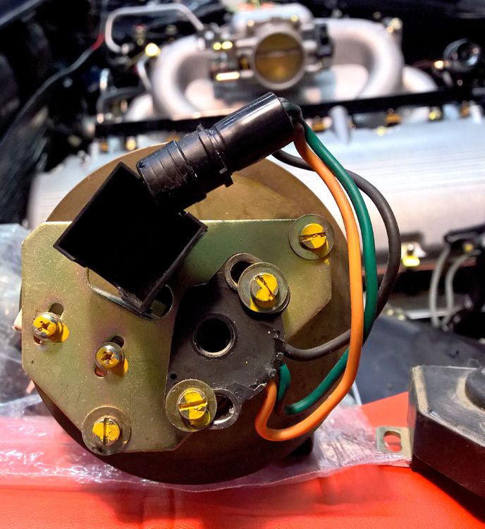
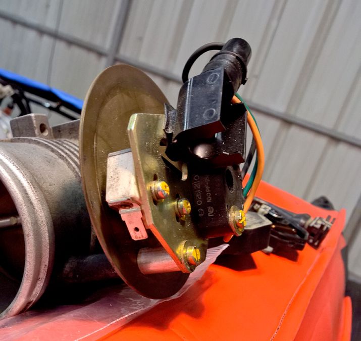
For edification, this is the what the Auto TPS looks like inside:


Inside this is the wiring:
(1) round barrel connector with an Orange, Green and Black wire; this connects to another barrel connector in the Harness
(1) block with two spade terminals that connector to two connectors in the Harness
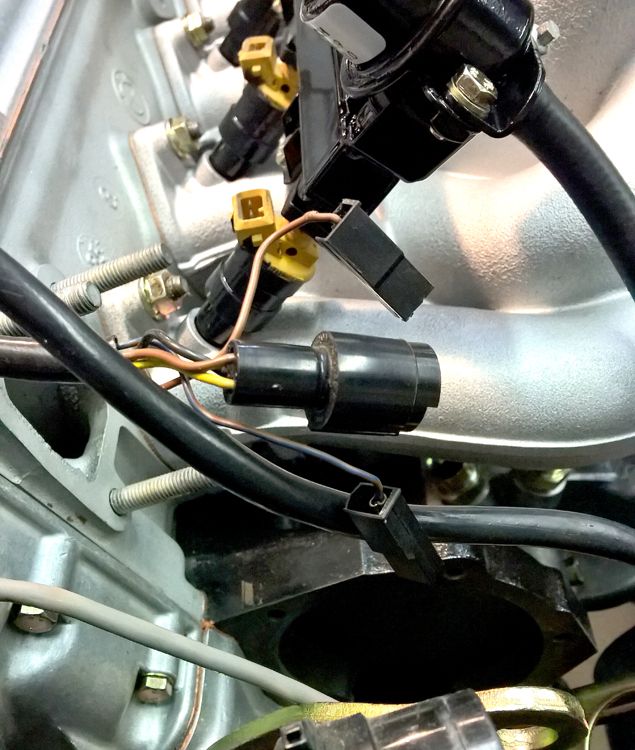
Here is the Wire Harness side:

It has:
(1) round barrel connector with a Yellow, Brown, and Black wire
(1) spade terminal connector with a Brown wire
(1) spade terminal connector with a Brown/Blue wire
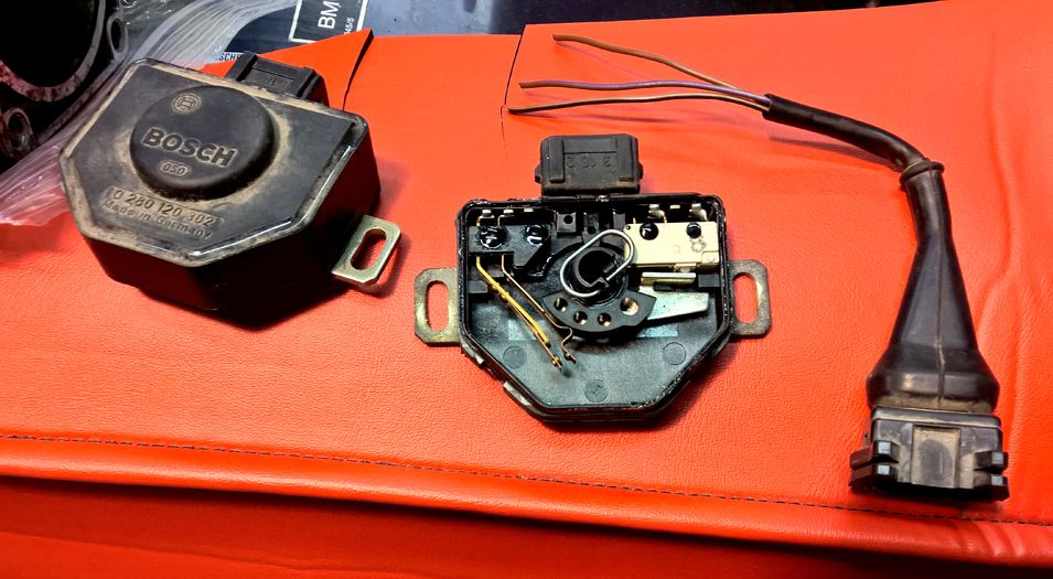
The Manual TPS looks this inside when you crack it open with the connector plug next to it that is present in a Manual Wire Harness:

The wires in Connector Plug are:
(1) Brown wire
(1) Brown/Black wire
(1) Brown/Violet wire
According to the ETM, a Manual TPS is wired as follows:
(1) Brown/Blue wire for closed throttle position
(1) Brown/Black wire for open throttle position
(1) Brown ground
And an Automatic TPS is wired thus:
(1) Brown/Blue for throttle position input
(1) Brown ground
So, like I said, I am looking for information and instruction on which wires to connect to what and which to ignore. At the very least some insight into matching the wires I see in the car to the ETM.
Any and all help is very welcome.
Thanks.
This was never done when the car underwent a Transmission swap to a 5-Speed way back when.
My issue and question is how to modify the car's existing Main Wire Harness which has the Auto TPS connectors by wiring into it the Manual Connector Plug. There are some seemingly conflicting issues I am having with the information in the ETM and what I see in the car. So I an unclear on which wires to pay attention to and which to ignore/cut/abandon. Note that there is no power to this car at the moment so forget running any electronic diagnostics or metering tests.
For edification, this is the what the Auto TPS looks like inside:


Inside this is the wiring:
(1) round barrel connector with an Orange, Green and Black wire; this connects to another barrel connector in the Harness
(1) block with two spade terminals that connector to two connectors in the Harness
Here is the Wire Harness side:

It has:
(1) round barrel connector with a Yellow, Brown, and Black wire
(1) spade terminal connector with a Brown wire
(1) spade terminal connector with a Brown/Blue wire
The Manual TPS looks this inside when you crack it open with the connector plug next to it that is present in a Manual Wire Harness:

The wires in Connector Plug are:
(1) Brown wire
(1) Brown/Black wire
(1) Brown/Violet wire
According to the ETM, a Manual TPS is wired as follows:
(1) Brown/Blue wire for closed throttle position
(1) Brown/Black wire for open throttle position
(1) Brown ground
And an Automatic TPS is wired thus:
(1) Brown/Blue for throttle position input
(1) Brown ground
So, like I said, I am looking for information and instruction on which wires to connect to what and which to ignore. At the very least some insight into matching the wires I see in the car to the ETM.
Any and all help is very welcome.
Thanks.